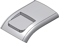
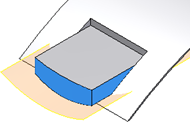
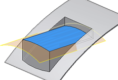
Before starting, create or import a thin-walled part with the rest profile on a 2D sketch between the upper and lower faces of the part.
If you plan to create a rest feature with a surface as the landing area, include a surface that spans the entire sketch at the position where the landing surface is required.
Tip: Use an Offset Work Plane for the sketch location.
- Click3D Model tab
 Plastic Part panel Rest
  .
. - Using the Profile and Solid selectors, click in the graphics window to choose one or more closed sketch profiles and, if there’s more than one solid in the part file, the target body.
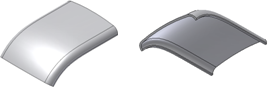
- In the Shape tab of the Rest dialog box, choose the platform extension type:
- Through All. (Default) Extends the platform to the next face of the target body.
- Distance. Specifies the height of the platform wall. Enter a value in the Distance field.
- To Surface. Extends the platform walls to the specified surface. Enter an Offset value.
- Through All. (Default) Extends the platform to the next face of the target body.
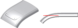
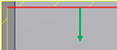
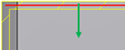
- If desired, click a Flip icon to reverse the direction of the platform/clearance.
The correct direction is usually the one that points to the inside of the target body unless the Both Sides option is selected. The goal is to maintain the landing profile on the outside of the body.
- Use the Thickness options to specify on which side of the rest offset to create the thin wall with respect to the sketch reference and the direction arrow:
- Inside.

- Outside.
- Both Sides.
- Inside.
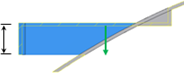
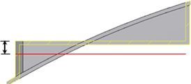
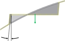
- On the More tab of the Rest dialog box, specify landing options:
- Distance. Specifies the distance of the landing from the sketch plane.
- To Surface. Specifies the surface on which to place the landing. Specify an Offset from the reference surface.
- Offset. Specifies an offset from the reference surface in the To Surface option.
- Landing Taper. Specifies a draft angle for the platform.
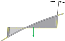
- Clearance Taper. Specifies a draft angle for the clearance walls.
- Distance. Specifies the distance of the landing from the sketch plane.
- Click OK.