Synopsis
Part Hole Features live as children of the target IvAdoptedPart. Part Hole Features are specified through four major categories: Operation, Type, Placement, and Termination.
Hole operation can be specified in one of four ways:
- Drilled - A hole without countersink, counterbore, or spotface. No parameters need to be specified.
- Countersink - A conical hole cut into the hole face at the hole center.
- Counterbore - A cylindrical hole cut into the hole face at the hole center.
- Spotface - A cylindrical hole cut into the hole face at the hole center.
Only one hole operation should be specified.
Hole type can be specified in one of three ways:
- Simple - A hole with no thread.
- Tapped - A tapped hole with parallel threading. The hole diameter is implicitly specified.
- Tapered - A tapped hole with tapered threading. The hole diameter is implicitly specified.
A parallel thread or a tapered thread may be specified for a hole. Since the threading dimensions are taken from a library of thread types/classes/designations, the diameter of the hole will, in these cases, be implicitly specified. If a parallel or tapered thread is not specified, the diameter can be explicitly specified; otherwise, it will default to 0.5.
Hole placement can be specified in one of four ways:
- Linear - The placement of a hole on a face by its distance to two edges. A bias point that is in the same quadrant with respect to the two edges as the intended hole is required. This bias point must also lie on the face.
- Concentric - The placement of a hole concentric with a circular edge or a cylindrical face.
- On Point - The placement of a hole by a work point and an entity that specifies the hole axis.
- From Sketch - The placement of holes by hole center points on a sketch. The factory part containing the sketch must be adopted into Intent. The sketch must be both visible and exported. For part holes, sketch placement creates a derived sketch part which is a child of the hole child.
Only one placement type should be specified.
Hole termination can be specified in one of three ways:
- Blind - The hole terminates at a specific depth.
- To - The hole terminates at the specified face.
- Through All - The hole continues indefinitely.
Only one termination type should be specified.
Mixins
IvFeature
IvPartHoleFeatureModifier
Parameters
| Name | Type | Description |
|---|---|---|
| diameter | number | Optional. The diameter of the hole. Default value = 0.5 |
| face | string | (Required for linear, concentric, and sketch placement) Name of planar face or work plane on which the hole is placed. |
| edge1 | string | (Required for linear placement) Name of the first edge from which hole center position is dimensioned. |
| distance1 | number | (Required for linear placement) Distance from edge1 to hole center. |
| edge2 | string | (Required for linear placement) Name of the second edge from which hole center position is dimensioned. |
| distance2 | number | (Required for linear placement) Distance from edge2 to hole center. |
| biasPoint | string | (Required for linear placement) Name of a point on face to help locate the hole center. |
| concentricReference | string | (Required for concentric placement) Name of circular edge or cylindrical face by which to determine the hole center; the hole center will lie at the center point of the circular edge or along the axis of the cylindrical face. If a circular edge is specified, it must lie on a plane parallel to the plane of face. If a cylindrical face is specified, its axis must be perpendicular to the plane of face. |
| centerPoint | string | (Required for point placement) Name of a WorkPoint that specifies the hole center. |
| direction | string | (Required for point placement) Name of an entity that specifies the direction of the hole axis. This can be a planar face or a WorkPlane with which the axis of the hole is perpendicular, or an edge or WorkAxis with which the axis of the hole is parallel. |
| sketchName | string | (Required for sketch placement) Name of sketch. |
| sketchPart | part | (Required for sketch placement) the part that contains sketchName. |
| origin | string | (Required for sketch placement) Name of vertex or work point, where sketch origin is placed. |
| xAxis | string | (Required for sketch placement) Name of edge or work axis, where sketch x-axis is placed. |
| reverseXdirection? | boolean | (Applies to sketch placement) Optional. If true, the sketch's x-direction is reversed. Default = False. |
| reverseSketchNormal? | boolean | (Applies to sketch placement) Optional. If true, the sketch's normal is reversed. Default = False. |
| drilledType | name | (Applies to drilled operation) Optional. A value of Drilled or Drilled_default explicitly indicates a drilled operation. Default = Drilled_default. |
| csinkDiameter | number | (Required for countersink operation) The diameter of the countersink. |
| csinkAngle | number | (Required for countersink operation) The angle of the countersink in degrees. |
| cboreDiameter | number | (Required for counterbore operation) The diameter of the counterbore. |
| cboreDepth | number | (Required for counterbore operation) The depth of the counterbore. |
| spotFaceDiameter | number | (Required for spotface operation) The diameter of the spotface. |
| spotFaceDepth | number | (Required for spotface operation) The depth of the spotface. |
| threadDesignation | string | (Required for parallel and tapered thread) The thread designation (e.g. "M16x1.5", "M55x1.5"). See Thread.xls in the Inventor install directory for a complete listing. |
| threadClass | string | (Required for parallel thread) The thread class (e.g. "2B"). See Thread.xls in the Inventor install directory for a complete listing. |
| parallelThreadType | string | (Applies to parallel thread) Optional. The parallel thread type (e.g. ?ANSI Metric M Profile"). See Part Editor or Thread.xls in the Inventor install directory for a complete listing. Default value = "ANSI Unified Screw Threads". |
| fullDepthThread? | boolean | (Applies to parallel thread) Optional. If True, indicates that the thread goes the full extent of the hole. Default value = True. |
| threadDepth | number | (Applies to parallel thread) Optional. Ignored unless fullDepthThread? is True. Specifies the depth of the threading within the hole. Default value = 1. |
| rightHanded? | boolean | (Applies to parallel and tapered thread) Optional. If true, the threading is right-handed. If false, it is left-handed. Default value = True. |
| taperThreadType | string | (Applies to tapered thread) Optional. The taper thread type (e.g. ?NPT?). See Part Editor or Thread.xls in the Inventor install directory for a complete listing. Default value = "NPT". |
| depth | number | (Applies to distance termination) Optional. Hole depth. Default value = 1. |
| extentDirection | name | (Applies to distance or Through All termination) Optional. Hole direction. :Positive, :Negative. Default value = :Positive |
| flatBottom? | boolean | (Applies to distance termination) Optional. If true, hole bottom is flat. Default value = True. |
| bottomTipAngle | number | (Applies to distance termination) Optional. Ignored if flatBottom? is false. The angle of the hole bottom's drill tip in degrees. Default value = 118. |
| toFace | string | (Required for To Face termination) Name of the termination face. |
| extendToFace? | boolean | (Applies to To Face termination) Optional. If true, extend toFace to fully include the hole. |
| throughAllType | name | (Required for Through All termination) :ThroughAll specifies a through hole. |
| NameFeatureGeometry? | boolean | Controls whether faces, edges, and vertices created by the feature will have names assigned to them for reference by other entities. |
Part Feature Entity Naming

There is an automatic entity naming mechanism for IvPartHoleFeature. The illustration shows the automatically-applied entity names as viewed in the Entity Naming Editor.
Example 1
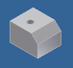
This example creates a part which must be added as a child of an Assembly Document. This part hole feature uses linear placement (face, edge1, edge2, biasPoint, distance1, distance2) and explicitly specified diameter.
| Name: | PartHole_Part01 |
| Design: | Part1Adopt |
| Child Name: | simpleLinearHole | |
| Child Design: | IvPartHoleFeature | |
| Name | Type | Supplied |
| drilledType | name | :Drilled |
| face | string | "TopFace" |
| edge1 | string | "TopFrontEdge" |
| edge2 | string | "TopLeftEdge" |
| distance1 | number | 10 |
| distance2 | number | 12 |
| biasPoint | string | "v001" |
| extentDirection | name | :Positive |
| diameter | number | 6 |
| throughAllType | name | :throughAll |
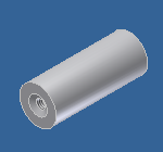
Example 2

This example creates a part which must be added as a child of an Assembly Document. This part hole feature uses concentric placement (concentricReference and face), explicitly specified diameter, and drilled operation (drilledType).
| Name: | PartHole_Part02 |
| Design: | Cyl1Adopt |
| Child Name: | simpleConcentricHole | |
| Child Design: | IvPartHoleFeature | |
| Name | Type | Supplied |
| drilledType | name | :Drilled |
| face | string | "fTop" |
| concentricReference | string | "eTop" |
| extentDirection | name | :Positive |
| diameter | number | 15 |
| throughAllType | name | :throughAll |
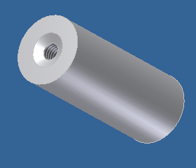
Example 3
This example creates a part which must be added as a child of an Assembly Document. This tapped part hole feature uses concentric placement (concentricReference and face), explicitly specified countersink diameter and angle, and parallel thread parameters (type, designation, and class).
| Name: | PartHole_Part03 |
| Design: | Cyl1Adopt |
| Child Name: | tappedConcentricHole | |
| Child Design: | IvPartHoleFeature | |
| Name | Type | Supplied |
| face | string | "fTop" |
| concentricReference | string | "eTop" |
| csinkAngle | number | 120 |
| csinkDiameter | number | 10 |
| parallelThreadType | string | "ISO Metric Profile" |
| threadDesignation | string | "M6x1" |
| threadClass | string | "6H" |
| flatBottom? | boolean | False |
| bottomTipAngle | number | 120 |
| depth | number | 72 |