Synopsis
Assembly Hole Features live as children of IvAssemblyDocument. Assembly Hole Features are specified through four major categories: Operation, Type, Placement, and Termination.
Hole Operation
Hole operation can be specified in one of four ways:
- Drilled - A default hole without countersink, counterbore, or spotface. No parameters need to be specified.
- Countersink - A conical hole cut into the hole face at the hole center.
- Counterbore - A cylindrical hole cut into the hole face at the hole center.
- Spotface - A cylindrical hole cut into the hole face at the hole center.
Hole Type
Hole type can be specified in one of three ways:
- Simple - A hole with no thread.
- Tapped - A tapped hole with parallel threading. The hole diameter is implicitly specified.
- Tapered - A tapped hole with tapered threading. The hole diameter is implicitly specified.
A parallel thread or a tapered thread may be specified for a hole. Since the threading dimensions are taken from a library of thread types/classes/designations, the diameter of the hole will, in these cases, be implicitly specified. If a parallel or tapered thread is not specified, the diameter can be explicitly specified; otherwise, it will default to 0.5.
Hole Placement
Hole placement can be specified in one of four ways:
- Linear - The placement of a hole on a face by its distance to two edges. A bias point that is in the same quadrant with respect to the two edges as the intended hole is required. This bias point must also lie on the face.
- From Sketch - The placement of holes by hole center points on a sketch.
- Concentric - The placement of a hole concentric with a circular edge or a cylindrical face.
- On Point - The placement of a hole by a work point and an entity that specifies the hole axis.
In assembly holes, any named entity (e.g. face, edge, etc.) must have an accompanying part . For example, in linear placement for an assembly hole feature, one must specify both edge1 and its containing part edge1Part.
Hole Termination
Hole termination can be specified in one of three ways:
- Blind - The hole terminates at a specific depth.
- To - The hole terminates at the specified face.
- Through All - The hole continues indefinitely.
Mixins
IvAssemblyFeatureDesign
IvAssemblyHoleFeatureModifier
Parameters
| Name | Type | Description |
|---|---|---|
| participants | any | The list of participants to which the hole feature is applied. If :AutoSelect, then all sibling parts are participants. Default value = :AutoSelect. |
| diameter | number | Optional. The diameter of the hole. Default value = 0.5 |
| face | string | (Required for linear and concentric placement) Name of planar face or work plane on which the hole is placed. |
| facePart | part | (Required for linear and concentric placement) The part that contains face. |
| edge1 | string | (Required for linear placement) Name of the first edge from which hole center position is dimensioned. |
| edge1Part | part | (Required for linear placement) The part that contains edge1. |
| distance1 | number | (Required for linear placement) Distance from edge1 to hole center. |
| edge2 | string | (Required for linear placement) Name of the second edge from which hole center position is dimensioned. |
| edge2Part | part | (Required for linear placement) The part that contains edge2. |
| distance2 | number | (Required for linear placement) Distance from edge2 to hole center. |
| biasPoint | string | (Required for linear placement) Name of a point on face to help locate the hole center. |
| biasPointPart | part | (Required for linear placement) The part that contains biasPoint. |
| concentricReference | string | (Required for concentric placement) Name of circular edge or cylindrical face by which to determine the hole center; the hole center will lie at the center point of the circular edge or along the axis of the cylindrical face. If a circular edge is specified, it must lie on a plane parallel to the plane of face. If a cylindrical face is specified, its axis must be perpendicular to the plane of face. |
| concentricReferencePart | part | (Required for concentric placement) The part that contains concentricReference. |
| centerPoint | string | (Required for point placement) Name of a Work Point that specifies the hole center. |
| centerPointPart | part | (Required for point placement) The part that contains centerPoint. |
| direction | string | (Required for point placement) Name of an entity that specifies the direction of the hole axis. This can be a planar face or a Work Plane with which the axis of the hole is perpendicular, or an edge or Work Axis with which the axis of the hole is parallel. |
| directionPart | part | (Required for point placement) The part that contains direction. |
| sketchName | string | (Required for sketch placement) Name of sketch. |
| sketchPart | part | (Required for sketch placement) the part that contains sketchName. |
| drilledType | name | (Applies to drilled operation) Optional. A value of Drilled or Drilled_default explicitly indicates a drilled operation. Default = Drilled_default. |
| csinkDiameter | number | (Required for countersink operation) The diameter of the countersink. |
| csinkAngle | number | (Required for countersink operation) The angle of the countersink in degrees. |
| cboreDiameter | number | (Required for counterbore operation) The diameter of the counterbore. |
| cboreDepth | number | (Required for counterbore operation) The depth of the counterbore. |
| spotFaceDiameter | number | (Required for spotface operation) The diameter of the spotface. |
| spotFaceDepth | number | (Required for spotface operation) The depth of the spotface. |
| threadDesignation | string | (Required for parallel and tapered thread) The thread designation (e.g. "M16x1.5", "M55x1.5"). See Thread.xls in the Inventor install directory for a complete listing. |
| threadClass | string | (Required for parallel thread) The thread class (e.g. "2B"). See Thread.xls in the Inventor install directory for a complete listing. |
| parallelThreadType | string | (Applies to parallel thread) Optional. The parallel thread type (e.g. ?ANSI Metric M Profile"). See Thread.xls in the Inventor install directory for a complete listing. Default value = "ANSI Unified Screw Threads". |
| fullDepthThread? | boolean | (Applies to parallel thread) Optional. If True , indicates that the thread goes the full extent of the hole. Default value = True . |
| threadDepth | number | (Applies to parallel thread) Optional. Ignored unless fullDepthThread? is True. Specifies the depth of the threading within the hole. Default value = 1. |
| rightHanded? | boolean | (Applies to parallel and tapered thread) Optional. If true , the threading is right-handed. If false , it is left-handed. Default value = True . |
| taperThreadType | string | (Applies to tapered thread) Optional. The taper thread type (e.g. ?NPT?). See Thread.xls in the Inventor install directory for a complete listing. Default value = "NPT". |
| depth | number | (Applies to distance termination) Optional. Hole depth. Default value = 1. |
| extentDirection | name | (Applies to distance or Through All termination) Optional. Hole direction. :Positive, :Negative. Default value = :Positive |
| flatBottom? | boolean | (Applies to distance termination) Optional. If true , hole bottom is flat. Default value = True . |
| bottomTipAngle | number | (Applies to distance termination) Optional. Ignored if flatBottom? is false . The angle of the hole bottom's drill tip. Default value = 118. |
| toFace | string | (Required for To Face termination) Name of the termination face. |
| toFacePart | part | Part that contains toFace. |
| extendToFace? | boolean | (Applies to ToFace termination) Optional. If true , extend toFace to fully include the hole. |
| throughAllType | name | (Required for Through All termination) :ThroughAll specifies a through hole. |
| NameFeatureGeometry? | boolean | Controls whether faces, edges, and vertices created by the feature will have names assigned to them for reference by other entities. |
Assembly Feature Entity Naming
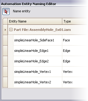
There is an automatic entity naming mechanism for IvAssemblyHoleFeature. The illustration shows the automatically-applied entity names as viewed in the Entity Naming Editor.
Example 1
This assembly hole feature uses linear placement (face, edge1, edge2, biasPoint, distance1, distance2) and explicitly specified diameter. The participants parameter specifies that the hole feature is only applied to Blk_Part1.
| Name : | AssemblyHole_Ex01 |
| Design : | IvAssemblyDocument |
| Child Name : | Blk_Part1 | |
| Child Design : | :Part1 | |
| Name | Type | Supplied |
| height | number | 20 |
| length | number | 30 |
| Child Name : | Blk_Part2 | |
| Child Design : | :Part2 | |
| Name | Type | Supplied |
| height | number | 12 |
| length | number | 30 |
| Child Name : | simpleLinearHole | |
| Child Design : | IvAssemblyHoleFeature | |
| Name | Type | Supplied |
| drilledType | name | :Drilled |
| face | string | "TopFace" |
| facePart | part | Blk_Part1 |
| edge1 | string | "TopFrontEdge" |
| edge1Part | part | Blk_Part1 |
| edge2 | string | "TopLeftEdge" |
| edge2Part | part | Blk_Part1 |
| biasPoint | string | "v001" |
| biasPointPart | part | Blk_Part1 |
| distance1 | number | 10 |
| distance2 | number | 12 |
| extentDirection | name | :Positive |
| diameter | number | 6 |
| participants | any | {Blk_Part1} |
Example 2

This assembly hole feature uses concentric placement (concentricReference and face), explicitly specified diameter, and drilled operation (drilledType). The hole feature is applied to all parts .
| Name : | AssemblyHole_Ex02 |
| Design : | IvAssemblyDocument |
| Child Name : | Cyl_Part1 | |
| Child Design : | :IvCylinder | |
| Name | Type | Supplied |
| height | number | 50 |
| radius | number | 10 |
| Child Name : | Cyl_Part2 | |
| Child Design : | :IvCylinder | |
| Name | Type | Supplied |
| height | number | 12 |
| radius | number | 10 |
| Child Name : | simpleConcentricHole | |
| Child Design : | IvPartHoleFeature | |
| Name | Type | Supplied |
| concentricReference | string | "eTop" |
| concentricReferencePart | part | Cyl_Part1 |
| face | string | "fTop" |
| facePart | part | Cyl_Part1 |
| diameter | number | 15 |
| extentDirection | name | :Positive |
| drilledType | name | :Drilled |
Example 3
This tapped assembly hole feature uses concentric placement (concentricReference and face), explicitly specified countersink diameter and angle, and parallel thread parameters (type, designation, and class).
| Name : | AssemblyHole_Ex03 |
| Design : | IvAssemblyDocument |
| Child Name : | Cyl_Part1 | |
| Child Design : | :IvCylinder | |
| Name | Type | Supplied |
| height | number | 50 |
| radius | number | 10 |
| Child Name : | Cyl_Part2 | |
| Child Design : | :IvCylinder | |
| Name | Type | Supplied |
| height | number | 15 |
| radius | number | 10 |
| Child Name : | tappedConcentricHole | |
| Child Design : | IvPartHoleFeature | |
| Name | Type | Supplied |
| concentricReference | string | "eTop" |
| concentricReferencePart | part | Cyl_Part1 |
| face | string | "fTop" |
| facePart | part | Cyl_Part1 |
| csinkDiameter | number | 10 |
| csinkAngle | number | 120 |
| parallelThreadType | string | "ISO Metric Profile" |
| threadDesignation | string | "M6x1" |
| threadClass | string | "6H" |
| flatBottom? | boolean | False |
| bottomTipAngle | number | 120 |
| depth | number | 72 |