You can query objects from one drawing into another drawing of the same geographical area, even if the drawings use different coordinate systems. The queried objects are automatically converted to the assigned coordinate system. If a drawing does not use a known coordinate system, align the objects to the map manually.
In this exercise, you georeference drawing objects by adding them to a map with a known coordinate system.
In practice, you can obtain such a map from the local county or municipality. For example, for a drawing of city parcels, obtain a digital version of an assessor map of that city. Make sure that you know the coordinate system used to create that map. We refer to this map as the “target map.” In this example, you connect to an SDF data store containing parcel information.
You use the Rubber Sheet command to align the drawing objects with known locations in the target map.
To georeference drawing objects
- Create a drawing and assign a coordinate system.
- Click

 NewDrawing.
- Select the map2d.dwt template and click Open.
- Assign a coordinate system. Click Map Setup tabCoordinate System panelAssign.
- In the Coordinate System - Assign dialog box, enter CA-I in the Search field and press Enter.
- Click the CA-I entry in the Code column and click Assign.
- Click
- Connect to a parcel data store of the same geographical area.
In this example, connect to the tutorial sample file PARCELS.SDF, which uses the coordinate system CA-I.
- Click Home tabData panelConnect to Data.
- Under Data Connections By Provider, select Add SDF Connection.
- Click the file icon next to Source File.
- Navigate to the folder where you copied the sample files and select PARCELS.SDF. Click Open.
- Click Connect to add the parcel data file as a data source.
- Click Add To Map.
- Close the Data Connect window.
- Click Home tab
- Open the drawing containing your drawing objects.
In this example, open the sample tutorial drawing subdivision_block.dwg, which has no coordinate system.
- In the
subdivision_block.dwg drawing, select and copy the objects to align.
The objects in subdivision_block.dwg are defined as a block.
- Click anywhere on the block perimeter to select all the objects.
- Click
. Find
- In the target map, paste the objects into the blank area in the center of the drawing.
- Switch the current window to the parcels drawing you created.
- Zoom into the empty area in the center of the drawing.
- In the empty area, right-click and select ClipboardPaste.
- Click an insertion point for the block.
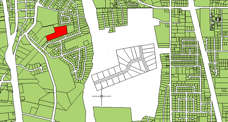
Paste the subdivision block in the empty space. Find the parcel to which the subdivision aligns. In this illustration, the parcel is red (but it is not red in the sample file).
- Find the points that the target map and the drawing objects have in common.
For example, if your drawing represents new parcels, find the development that contains those parcels. Find at least two common points.
In the parcels drawing you created, the parcel you want is to the left of the empty area. In the illustration above, it is red.
- Use the Rubber Sheet command to align your drawing objects with the known objects in the map.
- Zoom in as close as you can, while still displaying the target area and the subdivision drawing.
- Click

- When prompted on the command line for Base Point 1, click the first common point in your drawing object block.
- When prompted on the command line for Reference Point 1, click the corresponding point in the target map.
- For this tutorial, specify four reference points. When you are finished, press Enter.
The order in which you select the points and the spread of the points affects the results. For complex curved figures, more vertices result in a more accurate alignment.
- Select the object to align it with the reference area.
- Click Select in the dynamic input prompt, or enter s to select the objects to rubber sheet.
- Click the subdivision block to select it.
- Press Enter to complete the process.
Where you are now
You created a drive alias for drawings stored on a shared drive. You georeferenced drawing objects, using the Rubber Sheet command to align them with known locations.
To continue this tutorial, go to Lesson 2: Clean Up Your Drawings.