A Bifröst simulation consists of several object, property, and container nodes that are connected together. As you edit and refine a simulation, you will need to adjust attributes in several places. Although you can do most of the work using the Bifrost Fluids menu and the Attribute Editor, the Node Editor can be useful for understanding the relationships between the various elements.
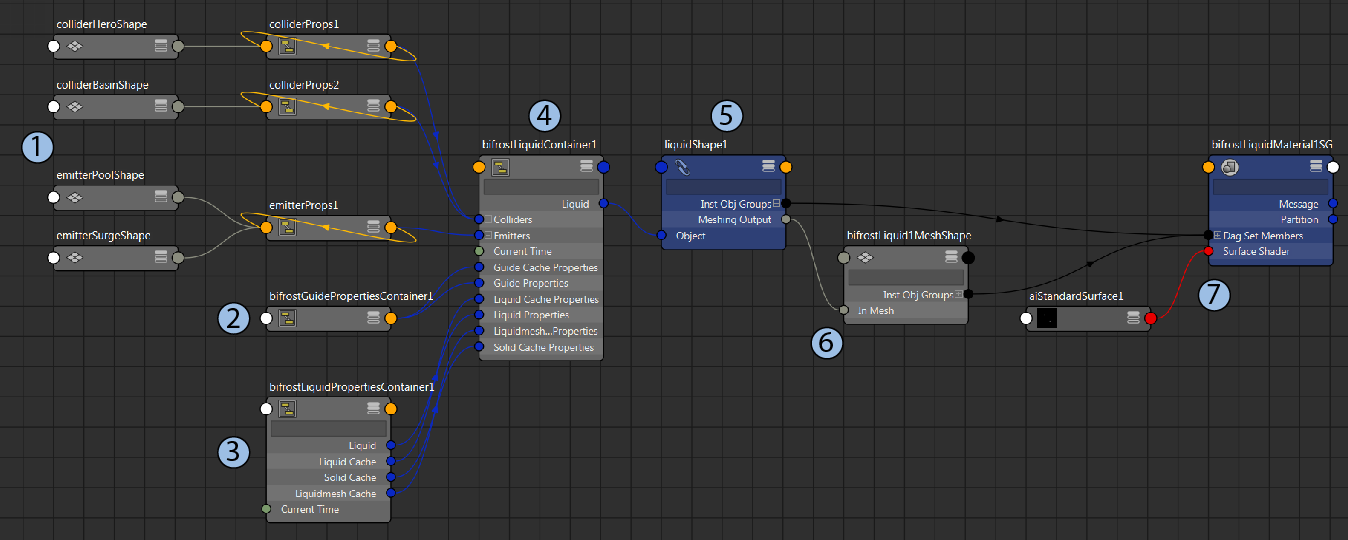
The image below is a simplified view of the node graph for a basic liquid simulation. Aero simulations involve some similar elements, but are generally simpler.

- 1. Colliders, emitters, and other meshes
-
This graph has two collider meshes and two emitter meshes that are connected to the main container through collider and emitter properties. There are similar properties for other mesh types that you can add to a scene. Each mesh property has attributes that are relevant to how the mesh is used in the simulation — for example, an emitter property has attributes for continuous emission, density, and more.
In this example, the collider meshes use separate property nodes. This allows them to use different settings. You can connect meshes in this way by adding them one at a time using the commands on the Bifrost Fluids menu.
The emitter meshes share the same emitter property. This means that they always use the same settings, and you do not need to adjust the settings on multiple properties. You can connect meshes in this way by adding them at the same time, or by selecting an existing property first.
You can change how meshes are connected by rewiring the graph, either adding new properties or deleted unwanted ones as required.
- 2. Global guide properties
- The global guide properties node contains the settings used for guided simulations. It is automatically created for all liquid graphs, but it does not get used unless you set up a guided simulation (see Guide a Bifröst simulation of a liquid surface).
- 3. Main properties
- The main properties node contains most of the settings that control the overall simulation. This includes the gravity, voxel size, and adaptivity, as well as other attributes that are specific to either liquid or aero simulations. The main properties node also has controls for reading and writing user cache files.
- 4. Main container
- The main container is the node that gets the property values from its inputs and performs the simulation. It has some attributes to control how and when the simulation is performed, such as for the start frame and scratch caching.
- 5. Shape
- The shape object is the representation of the result of the simulation in a scene. It has attributes for displaying the results as particles or voxels, as well as many diagnostic options. It also has attributes for activating and controlling how the result is meshed.
- 6. Mesh
- The mesh is another representation of the result. In addition to being rendered, it can be exported as an Alembic or other cache for use in another scene or software. Note that it has no polygons unless you activate meshing on the shape.
- 7. Material
- Different shaders might get applied to the shape by default, depending on your renderer. Some renderers, such as Arnold, can render the Bifröst shape directly. If you are using a renderer that does not support this, then you must render the mesh instead.