In the Animation menu set, select
Constrain > Motion Paths > Attach to Motion Path > ![]()
The selected object is placed on the selected curve, which becomes the motion path. See Attach an object to a Motion Path for information on how to constrain objects to motion paths.
- Time range
- These settings define the start and end times for the motion path along the curve.
- Time Slider
- Uses the values set in the Time Slider for the start and end of the motion path.
- Start
- Creates only one position marker at the start of the curve, or other value set in the Start Time field below. The object will be positioned at the beginning of the path, but the animation will not run until other position markers are placed along the path. You can use the Motion Path Manipulator Tool to add other position markers.
- Start/End
- Creates position markers at the start and end of the curve, with time values set in the Start Time and End Time fields below.
- Start Time
- Specifies the start time of the motion path animation. Only available when Start or Start/End in Time Range is on.
- End Time
- Specifies the end time of the motion path animation. Only available when Start/End in Time Range is on.
- Parametric Length
- Specifies the method Maya uses to position an object as it moves along a curve. There are two methods: parametric space and parametric length. Selecting
Parametric Length activates the parametric length method; deselecting it activates the parametric space method.
In the parametric space method, the markers represent positions in the U-parameter space of the curve. In the parametric length method, the markers represent positions as a percentage of the total curve length. The parametric length method is also known as the “fraction mode” method because the evaluation of the path is based on a fraction of the length of the path curve.
To understand the difference between the two methods, consider a curve that has uniform parameterization and unevenly spaced CVs.
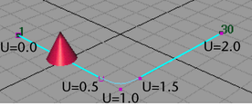
The curve above was created with five CVs and uniform knot spacing. The beginning of the curve is at U=0.0 and the end of the curve is at U=2.0. The cone was animated with path animation from time 1 to 30.
If the path animation for the cone is created with the parametric length method, the cone will move evenly along the curve from times 1 to 30.
If the path animation for the cone is created with the parametric space method, the cone moves quickly from the first to the second CV, then slowly through the second to fourth CV, then quickly again from the fourth to fifth CV. This is because the second and fourth CVs are positioned at approximately U=0.5 and U=1.5 parameterization points of the curve. These points take up half the total parameterization of the curve.
In parameter space, the object moves smoothly from U=0.0 to U=2.0. In world space, there is little movement of the object from (roughly) times 8 to 23, which coincide with the large parameter distance that must be covered in the correspondingly small curve length.
The advantage of using the parametric space method is that if you have spent time adjusting the timing of the object’s movement along the curve, CVs can be added to the beginning or end of the curve without affecting the timing of the motion on the existing part of the curve.
The advantage of using the parametric length method is that it is easy to obtain smooth timing of the object’s motion without having to insert timing markers to refine the timing of the object along the path curve.
- Follow
- If on, Maya computes the object’s orientation as it moves along the curve. It is on by default.
Maya uses a front vector and an up vector to compute the orientation of the object. Maya aligns the object’s local axes with the front vector and the up vector so that it knows how the object should be pointing upwards and forward as it moves along the curve.
At any point along the curve, the front vector aligns with the tangent to the curve, pointing in the direction of movement. The up vector is perpendicular to the tangent, but you must still tell Maya which perpendicular direction from the tangent is the up direction that you want. To do so, you specify a world up vector with which the up vector aligns. Use the World Up Type, World Up Vector, and World Up Object options to specify the world up vector.
You need to tell Maya which of the object’s local axes should be aligned with the front vector, and which should be aligned with the up vector. To view the object’s local axes, select the object and select . Next, specify which local axis aligns with the front vector with Front Axis. Also specify which local axis aligns with the up vector with Up Axis. Finally, you specify the type of world up vector (World Up Type) with which the up vector itself aligns.
The world up vector gives you the ability to control what the up vector considers to be the up direction. One benefit of this is that you can correct any sudden flipping problems as the object moves along the curve. For example, you can have the world up vector be the local axis of some other object such as a locator. You can then directly control the orientation of the world up vector by manipulating the locator.
Tip: When attaching an aimed camera to a curve as a motion path, turn off the Follow option. - Front Axis
- Specifies which of the object’s local axes X, Y, or Z, aligns with the front vector. This specifies the forward direction of travel along the motion path.
- Up Axis
- Specifies which of the object’s local axes (X, Y, or Z) aligns with the up vector. This specifies the upwards orientation of the object as it travels along the motion path. The up vector aligns with the world up vector specified by the World Up Type.
- World Up Type
- Specifies the type of world up vector that the up vector aligns with. Selections include
Scene Up,
Object Up,
Object Rotation Up,
Vector, and
Normal:
- Scene Up
- Specifies that the up vector tries to align with the scene’s up axis instead of the world up vector. The world up vector is ignored. You can specify the scene’s up axis in the Preferences window. The default scene up axis is the world space positive Y-axis.
- Object Up
- Specifies that the up vector tries to aim at the origin of a specified object instead of aligning with the world up vector. The world up vector is ignored. The object is called the world up object, and can be specified with the World Up Object option. If no world up object is specified, the up vector tries to aim at the origin of the scene’s world space.
- Object Rotation Up
- Specifies that the world up vector is defined relative to some object’s local space instead of the scene’s world space. The up vector tries to align with the world up vector after transforming it relative to the scene’s world space. The object whose origin the up vector tries to aim at is called the world up object. You can specify the world up object with the World Up Object option.
- Vector
- Specifies that the up vector tries to align with world up vector as closely as possible. By default, the world up vector is defined relative to the scene’s world space. Use World Up Vector to specify the direction of the world up vector relative to the scene’s world space.
- Normal
- specifies that the axis specified by
Up Axis will try to match the normal to the path curve. The interpretation of the curve normal is different, depending on whether the path curve is a curve in world space, or a curve on surface curve.
If the path curve is a curve in world space, then the normal of the curve is the direction that points to the center of curvature of the curve at any point on the curve. This is best illustrated by the arrows in the diagram below, which indicate the normal to the curve at various points:
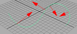
Note that the normal to a curve will flip 180 degrees when the curve changes from a convex to concave (or vice versa) shape. This makes the Normal option for the Up Direction not very desirable when using a world-space curve in your path animation.
If the path curve is a curve-on-surface, then the normal to the curve is the normal to the surface at that point on the curve. The Normal option will give the most intuitive results when the path curve is a curve-on-surface.
- World Up Vector
- Specifies the direction of the world up vector relative to the scene’s world space. Because Maya’s world space is “Y-up” by default, the default world up vector points in the direction of the world space’s positive Y-axis (0.0000, 1.0000, 0.0000).
- World Up Object
- Specifies the object the world up vector tries to align with if World Up Type is set to Object Up or Object Rotation Up. For example, you could specify the world up object as a locator that you can rotate as needed to prevent any sudden flipping problems as the object moves along the curve.
- Inverse Up
- If this option is on, Up Axis tries to align itself with the inverse of up vector.
- Inverse Front
- Reverses the forward direction an object is facing along the curve. This is especially useful when you are trying to orient a camera so that it points forward along a curve. If the camera points backwards along the curve, you can click Inverse front to make the camera point forward along the curve as desired.
- Bank
- Banking means the object will lean in towards the center of the curvature of the curve that it travels along, like a motorcycle going around a corner. The bank option is only available if the
Follow option is on, as banking also affects the rotations of the object.
The path animation automatically computes how much banking should occur depending on how curved the path curve is. You can adjust the banking using Bank Scale and Bank Limit.
- Bank Scale
- If you increase the
Bank Scale, then the banking effects will be more pronounced. For example, if the Bank Scale is set to 2, then the object will bank twice as much as the default.
Note: You can enter a negative number for Bank Scale. This will cause the object to lean out, away from the center of the curvature of the curve, rather than in towards the curvature. For example, you could use this when animating characters thrown from side to side in a roller coaster.
- Bank Limit
- The
Bank Limit lets you restrict the amount of leaning. For example, the
Bank Scale may be increased to obtain pronounced effects, but then this may cause the object to lean too much where the curve is very curved. This option will limit the leaning to the given amount.
Note: No banking occurs where the curve is a straight line.