Modify sub-d objects

Modify objects using the contextual modeling tools
This video demonstrates the contextual modeling tools in the Sub-d Patch, Volume, and Disc tools.
Video contents
- 0:04 - About the Sub-d contextual modeling tools
- 1:12 - Insert sub-d edges
- 1:45 - Extrude sub-d patch edges
- 2:31 - Extrude sub-d volume faces
- 3:31 - Extrude sub-d edges and faces along the X, Y, or Z axis
- 3:41 - Weld sub-d vertices and edges
- 3:50 - Guidelines for merging sub-d vertices and edges
- 4:35 - Weld sub-d faces
After creating a sub-d object, several tools for modifying the sub-d automatically become active when you bring the tool sphere close to an edge, CV, or face. These contextual modeling tools are embedded in the Sub-d Patch, Volume, and Disc tools and let you begin shaping your primitive right away. For example, you can move vertices, extrude boundary edges, insert edges, and weld vertices, edges, or faces without having to open the menu to select a new tool.
While modeling your sub-d, the active tool is determined by the position of the tool sphere on the object. A tool hint also displays to indicate which tool is active.
These tools are also available as individual modeling tools in the Tool Menu. Use the individual modeling tools to continue shaping your sub-d objects after you exit a sub-d creation tool. For information about using the individual modeling tools, jump to the following:
Modify sub-d objects using the individual modeling tools.
Modeling tips
- While shaping your primitive, turn on Box mode shading (
 ) to better detect any surface quality problems, such as odd-sized faces, uneven edges, or other surface irregularities.
 - Use the Quick Menu to access tools that are relevant to your current selected tool and task. Access the Quick Menu by pressing up on the Global Hand analog stick (Oculus) or D-pad (VIVE). Pointing the Tool Hand towards the Quick Menu will automatically cast a ray and you can select your desired tool by pulling the Tool Hand trigger.
Insert edges
- Hover the tool sphere over an existing edge until a row of green vertices appear.
- Drag the row of vertices along the edge to place the new edge, and then pull the trigger.
For information about moving sub-d object components, see Move sub-d CVs, edges and faces.
Extrude sub-d objects
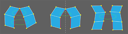
Extrude patch boundary edges
Hover the tool sphere over a boundary edge until it highlights and the Extrude tool hint appears.
The Extrude tool has three edge selection modes, indicated by the Extrude tool hint.
Tap right or left on the analog stick (Oculus) or D-pad (VIVE) to choose a selection mode:
Extrude (One) - Selects a single boundary edge.
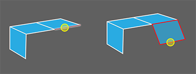
Extrude (FullSide) - Selects all edges along the boundary edge loop. Use this method to extrude the full edge loop including edges that are between corner vertices.
Extrude (Smart) - Selects edges along the boundary edge loop that are between corner vertices. Use this method to exclude edges attached to corner vertices so that sharp corners are not included in the extrusion.
Pull and hold the trigger, then drag to extrude.
To extrude in the X, Y, or Z directions, drag the extruded surface until the dashed guide lines change color to red for the X axis, blue for the Y axis, or green for the Z axis.
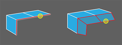
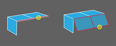
Extrude volume faces
Hover the tool sphere over a face until it pulses.
The Extrude tool has three face selection modes, indicated by the Extrude tool hint.
Tap right or left on the Tool Hand analog stick (Oculus) or D-pad (VIVE) to choose a selection mode:
- Extrude (One) - Selects a single face.
- Extrude (Corners) - Selects all faces, including faces attached to creased edges.
- Extrude (Smart) Selects all faces, but excludes faces attached to creased edges.
Pull and hold the trigger, then drag to extrude.
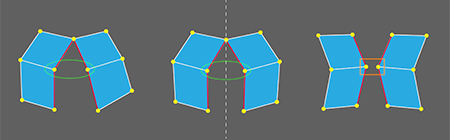
Weld subdiv components
- To weld patch boundary vertices or edges, hover the tool sphere over two vertices or edges, and then pull the trigger to weld after they highlight and the Weld tool hint appears.
- To weld patch or volume faces, hover the tool sphere over to adjacent faces, and pull the trigger to weld when the faces turn green and the Weld tool hint appears.
When welding vertices and edges be aware of the following:
You can only merge boundary vertices that share a common third CV on the boundary. You cannot weld neighboring or adjacent CVs.
You can merge any boundary edges.
Before merging boundary edges, ensure that the surface normals on each surface are pointing in the same direction. If you see that one of the surfaces displays a striped pattern while the other one does not, the normals are pointing in opposite directions. Use the Flip Normals tool to correct this before welding (see Flip surface normals). Otherwise, the weld will fail, or if successful, a twist in the surface will result.
Modify sub-d objects using the individual modeling tools
After you exit a sub-d creation tool, you can continue shaping your sub-d objects using these individual sub-d modeling tools:
Insert edges
Delete CVs, edges and faces
Extrude edges and faces
Split edges and faces
Bridge faces
Crease edges
Insert edges
- Select the Insert Edge Loop tool
 .
. - Hover over an edge or face on a sub-d object.
- Pull the Tool Hand trigger to insert an edge loop.
For information about moving sub-d object components, see Move sub-d CVs, edges and faces.
Delete CVs, edges and faces
Use the Delete Sub-d Components tool to remove sub-d CVs, edges and faces.
Select the Delete Sub-d Components tool
 .
.Do one of the following:
Hover the tool sphere over a CV.
Hover the tool sphere over an edge, and tap right or left on the analog stick (Oculus) or D-pad (VIVE) to choose a selection mode:
- Delete Edge (Multi-select) - Selects specific edges. Hold the trigger and drag over multiple edges to manually select them.
- Delete Edge (Edge Loop) - Selects an edge loop for modification.
Hover the tool sphere over a face, and tap right or left on the analog stick (Oculus) or D-pad (VIVE) to choose a selection mode:
- Delete Face (One) – Selects a single face.
- Delete Face (Smart) – Selects all faces on a flat surface.
- Delete Face (Face Loop) – Selects all faces along a face loop.
- Delete Face (Corners) – Selects all faces on a flat surface, including faces attached to creased edges.
Faces and edges to be deleted should be highlighted in red.
Place the stylus on the selection and pull the trigger.
Extrude edges and faces
Use the individual Extrude tool to extrude from curves, sub-d boundary edges and faces. The individual Extrude tool provides the same edge and volume selection modes as the contextual Extrude tool. For face extrusions, the individual Extrude tool includes an additional face selection mode: Multi-Select mode.
Extrude a sub-d from a curve
You can use the Extrude Sub-d tool to extrude a sub-d patch from a curve.
From the sub-d tools, select the Extrude tool
 .
.Hover the tool sphere over the curve until a wavy line displays.
Pull the trigger, drag, and then release to complete.
Continue to shape the sub-d patch by extruding its boundary edges.
Extrude patch edges
For information about extruding patch edges, see Extrude patch boundary edges .
Extrude patch and volume faces
Select the Extrude Sub-d Tool and hover the tool sphere over a face until it highlights.
Tap left or right on the Tool Hand to choose a selection mode:
Extrude (One) - Selects a single face.
Extrude (Corners) - Selects all faces, including faces attached to creased edges.
Extrude (Smart) - Selects all faces, but excludes faces attached to creased edges.
Extrude (Multi-select) - Selects multiple faces.
Note:Only internal faces can be extruded on patch primitives.
Pull the trigger and drag to extrude the selected faces.
To extrude in the X, Y, or Z directions, drag the extruded surface until the dashed guide lines change color to red for the X axis, blue for the Y axis, or green for the Z axis.
Split edges and faces
Use the Multi-Cut tool to split sub-d edges and faces. You can choose to use a vertex or a point along an edge as the start of your cut.
Select the Multi-Cut tool
 .
.Hover over an edge or vertex as the starting point of your cut.
The tool hint indicates which components will be used to start the cut.
Pull the trigger and drag the cut line across the face to an adjacent vertex or edge.
Press
 to complete the cut or repeat step 3 to continue cutting across more faces.
Bridge faces
Bridge two sub-d faces or curves by adding intermediate faces and edges between them. Bridge can be used to patch any triangle hole in a single sub-d object.
- Select the Bridge tool
 .
. - Hover over the first source edge(s), then pull the trigger on the first edge and drag to paint-select. Release the trigger to complete your selection.
- Hover over the target edge(s), then pull the trigger and drag to paint-select the same number of edges.
- Release the trigger to bridge the edges.
Crease edges
Apply a crease to one or more edges.
Select the Crease tool
 .
.Hover the tool sphere over an edge, and tap right or left on the analog stick (Oculus) or D-pad (VIVE) to choose a selection mode:
Crease (Multi-select) – Selects specific edges. Hold the trigger and drag over multiple edges to manually select them.
Crease (Edge Loop) – Selects an edge loop to crease.
Crease (Two-handed Chain-select) – Use both the Tool Hand and Global Hand to hover over the start and end point of a chain of edges to crease.
Edges to be creased are highlighted with a wavy line.
Pull the trigger to apply the crease.
To remove a crease, hover over the creased edge and pull the trigger.