Use the attributes in this section to apply built-in shading effects to the fluid.
In most cases, it’s better to use the built-in texturing (in the Textures section), however normal texturing works and should have good results in the case of 2D fluids. For 3D fluids, the textures will map to the entry points of the volume samples. To make a solid texture better represented within the volume, you can increase the volume samples using Volume Samples Override in the Render Stats section of the Attribute Editor.
- Transparency
-
Transparency combined with Opacity determines how much light can penetrate the defined Density. Transparency scales the single channel Opacity value. Using Transparency you can adjust the Opacity and also set its color.
You could adjust the Opacity of a fluid by moving the Transparency slider, ignoring all the other controls.
Note:A transparency of 0.5 0.5 0.5 may render slightly faster than other values.
- Glow Intensity
-
Controls the brightness of the glow (the faint halo of light around the fluid). Glow Intensity is 0 by default, so no glow is added to the fluid. As you increase the Glow Intensity, the apparent size of the glow effect increases.
Glow Intensity is different from the Incandescence attribute in two important ways:
- Glow is added as a post-process at the end of rendering. (Incandescence just makes the surface appear brighter.)
- Glow Intensity adds a halo. Incandescence does not.
- Dropoff Shape
-
Defines a shape to use to define an outer boundary for creating a soft edged fluid.

Setting Dropoff Shape to Use Falloff Grid lets you can define an arbitrary falloff region. When Use Falloff Grid is selected for emitted fluids, the fluid does not appear in the volume. See Define an arbitrary falloff region for fluid containers.
- Edge Dropoff
-
Defines the rate at which the Density values drop off towards the edges defined by the Dropoff Shape. A value of 0.0 results in no dropoff. As the value increases, the Density fades smoothly from the center to the edge of the dropoff shape.

Color
The Color ramp defines a range of color values used to render the fluid. The particular colors selected from this range correspond with the values for the selected Color Input. Color Input values of 0 map to the color at the left of the ramp, Color Input values of 1 map to the color at the right of the ramp, and values between 0 and 1 map to the color corresponding with the position on the ramp (relative to the Input Bias). The color represents how much incoming light is absorbed or scattered. If it is black, all light is absorbed, while white fluids scatter all incoming light.
For more information on using color ramps, see these topics:
- Selected Position
-
This value indicates the position of the selected color on the ramp (between 0 on the left to 1 on the right).
- Selected Color
-
Indicates the color on the ramp at the selected position. To change the color, click the Selected Color box and select a new color from Color Chooser.
Interpolation
Controls the way colors blend between positions on the ramp. The default setting is Linear.
- None
-
There is no interpolation between colors. Each color is distinct.
- Linear
-
The values are interpolated with a linear curve in RGB color space.
- Smooth
-
The values are interpolated along a bell curve so that each color on the ramp dominates the region around it, then blends quickly to the next color.
- Spline
-
The values are interpolated with a spline curve, taking the colors at neighboring position markers into account for a smoother transition.
Color Input
Defines the attribute used to map the color value.
- Constant
-
Sets the color in the entire container to the color at the end of the ramp (1.0).
- X, Y, Z, and Center Gradient
-
Sets the color in the entire container to a gradient corresponding with the ramp colors (from 1 to 0).
The other options all set the Color Input to the color corresponding with the value from the grid. For example if Density is the Color Input, the color at the start of the color ramp is used for Density values of 0 and the color at the end of the ramp for Density values of 1.0. Midrange values map according to the Input Bias.
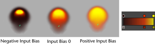
- Input Bias
-
Color Input Bias adjusts the sensitivity of the selected Color Input. Input values of 0 and 1 always map to the start and end of the ramp, while the bias determines where in the ramp a value of 0.5 maps. If the Input Bias is 0.0 then a Color Input value of 0.5 maps to the exact middle of the color ramp. Instead of values that are very close using the color at one part of the ramp, you can use the full range of colors to represent the values.
For example, if Density is the Color Input and the Density values in the container are all close to 0.1, you can use the Input Bias to shift the ramp color range so the Density values around 0.1 can be differentiated using the full range of colors on the ramp. If you do not change the Input Bias, the differences in color for values close to 0.1 could be indistinguishable.
Incandescence
Incandescence controls the amount and color of light emitted from regions of Density due to self illumination. The particular colors selected from this range correspond with the values for the selected Incandescence Input. Incandescent emission is not affected by illumination or shadowing.
The Incandescence ramp defines a range of incandescent color values. The particular colors selected from this range correspond with the values for the selected Incandescence Input. Incandescence Input values of 0 map to the color at the left of the ramp, Incandescence Input values of 1 map to the color at the right of the ramp, and values between 0 and 1 map to the color corresponding with the position on the ramp (relative to the Input Bias).
The Incandescence settings for position, color, interpolation, incandescence input, and input bias apply in the same way as they do for Color, described above.
Opacity
Opacity represents how much the fluid blocks light. The Opacity curve defines a range of opacity values used to render the fluid. The particular opacity values selected from this range are determined by the selected Opacity Input.

The vertical component represents the Opacity values from 0 (totally transparent) to 1 (totally opaque), the horizontal component represents Opacity Input values from 0 to 1. By clicking on the graph and dragging the points, you make a curve that defines what the opacity is for any input value. The default is a linear 1-1 relationship—input values (for example, Density) of 0 have no opacity, values of 0.5 have an opacity of 0.5, values of 1 have an opacity of 1. For more information on using single-value ramps like this, see Set attributes using ramps.
Density is the default Opacity Input, and the default linear curve makes the Opacity exactly equal to the Density. Given that you cannot get more opaque than 1.0, Densities greater than 1.0 are totally opaque. This simulates the total saturation of a fluid (that is, so much smoke you have a block of solid carbon).
To give Density hard edges, like the edges on thick clouds, you can edit the Opacity curve to threshold out the thin Density (low Density values) and define a hard falloff. If you are dealing with very thin Density, positioning the markers on the curve for the desired falloff might involve the markers being very close together all the way to one edge of the curve. The Input Bias attribute allows you to define the general look of the function with an easy-to-read layout (that is, without crowding the values), and then affect the input range to map it to the desired part of the function.
Texturing is also applied to the inputs to opacity rather than the output. This allows you to use the Opacity curve to apply hard edges to the texture, rather than texturing a hard edged Density. The gain on the texture is simply how the texture affects opacity—small gain, small effect.
You could adjust the opacity of a fluid by moving the Transparency slider, ignoring all the other controls.
The Opacity settings for position, color, interpolation, input, and input bias apply in the same way as they do for Color, described above.
Matte Opacity
The attributes in this section control how this fluid shows up in the matte (alpha channel or mask) when you render with one. This is useful if you will be compositing your rendered images.
Matte Opacity Mode
Select how Maya uses the Matte Opacity value.
- Black Hole
-
The Matte Opacity value is ignored, and all the matte for this fluid is set to be transparent. Use this option when you use substitute geometry in a scene to stand in for objects in a background image that you will be compositing with later. Your stand-in objects will ‘punch a hole’ in the matte. This allows other computer-generated geometry to pass behind your stand-in objects. Later, when foreground and background are composited, the results will be correct, with the background object showing through the ‘black hole’ areas.
- Solid Matte
-
The entire matte for the fluid is set to the value of the Matte Opacity attribute. This option is like Opacity Gain, except that the normally-calculated matte values are ignored in favor of the Matte Opacity setting. If there are transparent areas on the object, the transparency in these areas is ignored in the matte. Use this setting to composite an object with transparent areas, when you don’t want the background to show through them.
- Opacity Gain
-
Matte values are calculated based on the transparency of the object then multiplied by the Matte Opacity value. With Opacity Gain, you can animate the Matte Opacity value to change the overall transparency of the object when it is later composited.
Matte Opacity has a default value of one, so by default Solid Matte and Opacity Gain have no effect.
- Matte Opacity
-
Matte Opacity is used with Matte Opacity Mode to affect how the matte (alpha channel or mask) for this fluid is calculated.