Use these options to set the behavior and appearance of your surface flow effect.
Flow Along Surface
- Flow Group Name
-
Name of the Surface Flow node to contain the emitter, emitted particle object and other items added to the scene after you use the Surface Flow effect. To edit the Surface Flow attributes after you use the Surface Flow effect, you can select this name in the Outliner then display the Attribute Editor. If you don’t enter a name, Maya creates a default name.
You can delete all objects created by the Surface Flow effect by deleting the Curve Flow node from the Outliner.
Flow Creation Controls
- Create Particle
-
If on, particles are created for the flow on the selected surface. If off, no particles are created. One exception is if you have particles from an existing flow selected. If you do, the selected particles are applied to the new flow, whether this option is on or off. Do this if you want to connect particles from an existing flow with a new one.
- Create Particle Per Flow
-
If you have multiple surfaces selected and you want to create a separate flow for each selected surface, turn this option on. Turn this option off to create one flow across all selected surfaces.
- Manipulators Along
-
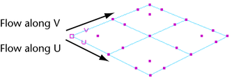
Sets the direction of the flow. The direction is specified in the U / V coordinate system, which is local to the surface. Positive U or V is forward, while negative U or V is backward. You can see which direction is U or V by selecting the model and switching to Component mode (but you must be out of Component mode when you create the effect).

- Control Resolution
-
Sets the number of flow manipulators. Flow manipulators let you control particle speed, distance from surface, and other settings for a specified area. By default, all flows have at least two manipulators for the beginning and end. Specify more manipulators depending on how many areas along the surface you want to control. However, the more manipulators you specify, the longer it takes to create.

- Sub-Control Resolution
-
Sets the number of sub manipulators between each flow manipulator. Sub manipulators control the flow of particles, but you cannot manipulate them directly. They are automatically spaced between flow manipulators to follow the curve of the surface. The more your surface varies along the direction of flow, the more sub manipulators you should have. However, the more sub manipulators you specify, the longer it takes to create.
- Manipulator Resolution
-
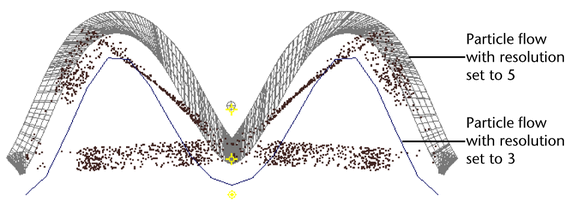
Sets the number of analysis points the flow manipulators use to direct particles. The more your surface varies along the manipulator, the greater your resolution should be.
The following illustration shows the front view of a surface with two flows, but different Manipulator Resolution settings. A resolution of 5 created the particles on top, while a resolution of 3 created the particles on the bottom.

Flow Attribute Controls
- Emission Rate
-
Sets the rate at which particles are emitted per unit of time.
- Particle Lifespan
-
Sets how many seconds each emitted particle exists from the beginning of the curve to the end. Higher values make the particles move slower.
- Goal Weight
-
Each emitted particle has a goal position that it follows as it moves along the path. The goal weight sets how precisely the particles track their goals. A weight of 1 makes the particles follow their goals exactly. Lower values diminish how closely they follow.
- Min Age Ratio, Max Age Ratio
-
Specifies what part of the total particle lifespan occurs in the flow—a ratio of flow lifespan to total lifespan. For example, if you set the Max Age Ratio to 0.5, the particles flow along the surface for half their lifespan and then continue beyond the last flow manipulator.