-
In the Animation or Rigging menu set: Constrain > Proximity Pin >

This topic covers the options in the Proximity Pin window. To create a proximityPin node, see Create a Proximity Pin.
Connections
- Input
- Sets the input matrix connection on the
Proximity Pin node in the
Node Editor.
New Locator Duplicates the selected transforms as locators called pinInput andconnects them to the proximityPin node's input. (This is the default.) Existing Transform Uses the selected transforms and connects them to the proximityPin node's input. New Transform Duplicates the selected transforms as transforms called pinInput and connects them to the proximityPin node's input. Matrix Adds input plugs to the node without connecting locators or transforms. Note: You can also add new input Matrices in the Attribute Editor. - Output
- Sets the Output matrix connection.
Existing Transform Uses the selected transforms and connects them to the proximityPin node's output. (This is the default.) New Locator Creates a new locators at the closest points on the surface and connects them to the node's output. New Transform Creates new transforms at the closest points on the surface and connects them to the node's output. Matrix Creates, but does not connect, any input plugs on the node, leaving the connection available.
Coordinate System
The Coordinate System area lets you set how the pin coordinates are derived from the geometry surface. Because Proximity Pin is procedural, you can continue to edit these settings in the Attribute Editor after creation.
- Mode
- Specifies how the coordinate system is derived from the surface.
- UV Set
- Specifies a UV set to be used for the coordinate system when the mode is set to UV.
- Normal axis
-
Specifies what axis of the coordinate system of the outputs to align with the surface normal. Cannot be the same as Tangent axis.
- Tangent axis
- Specifies what axis of the coordinate system of the outputs to align with the surface tangent. Cannot be the same as Normal axis.
- Maintain Offset
- Preserves the initial offset between the input matrix and the Original Geometry. After creation, the Attribute Editor lets you control the translation and orientation of the offset independently and supports fractional amounts. If you activate Maintain Offset in the Proximity Pin window, they are both initially set to 1. If you disable Maintain Offset, the translation and orientation offsets are both initially set to 0.
Attribute Editor options
The Attribute Editor Proximity Pin tab contains extra settings that are not covered in the Connections and Coordinate System sections.
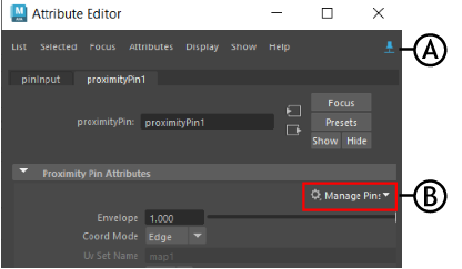
- Manage Pins
-

-

Attribute Editor: A. Pin Tab, B. Manage Pins menu
- Use this menu to manage operations you can apply to pin nodes. Choose from the following actions:
Select Geometry Selects the geometry affected by the UV pin. Replace Geometry with Selected Switches the pinned geometry with another selected geometry. Create Pins Creates a new PinOutput node. Select a node (locator/geometry/group, and so on) and the Pin node outputs a pin value, connecting it to the node (depending on the Pin default setting). Edit Pin Defaults Opens the UV Pin window, where you can set new values for the default pins: Existing Transform, New Transform, New Locator, or Matrix. Note: It is recommended to use the Attribute Editor Pin Tab while using this menu to keep the current attribute tab displayed when the selection changes.
- Envelope
- How much transformation to apply. 1.0 is full transformation and 0.0 is no transformation.
- Coordinate Mode
- Same setting as Mode in the Coordinate System area, above.
- Offset Translation
- Controls the amount of the original surface offset to use. 1.0 keeps full bind translation offset, and 0.0 forces the object to stay on the surface.
- Offset Orientation
- Controls the amount of original surface offset to use. A value of 1.0 keeps the full bind orientation offset, and a value of 0.0 uses the orientation derived from the surface.
- Normal Override
-
Set Normal Override to Rail to let you connect the Proximity Pin constraint to Rail Curve geometry.
