Define the toolpathing rules and generate a TOOLPATHXML file using the Graphical Toolpath Editor.
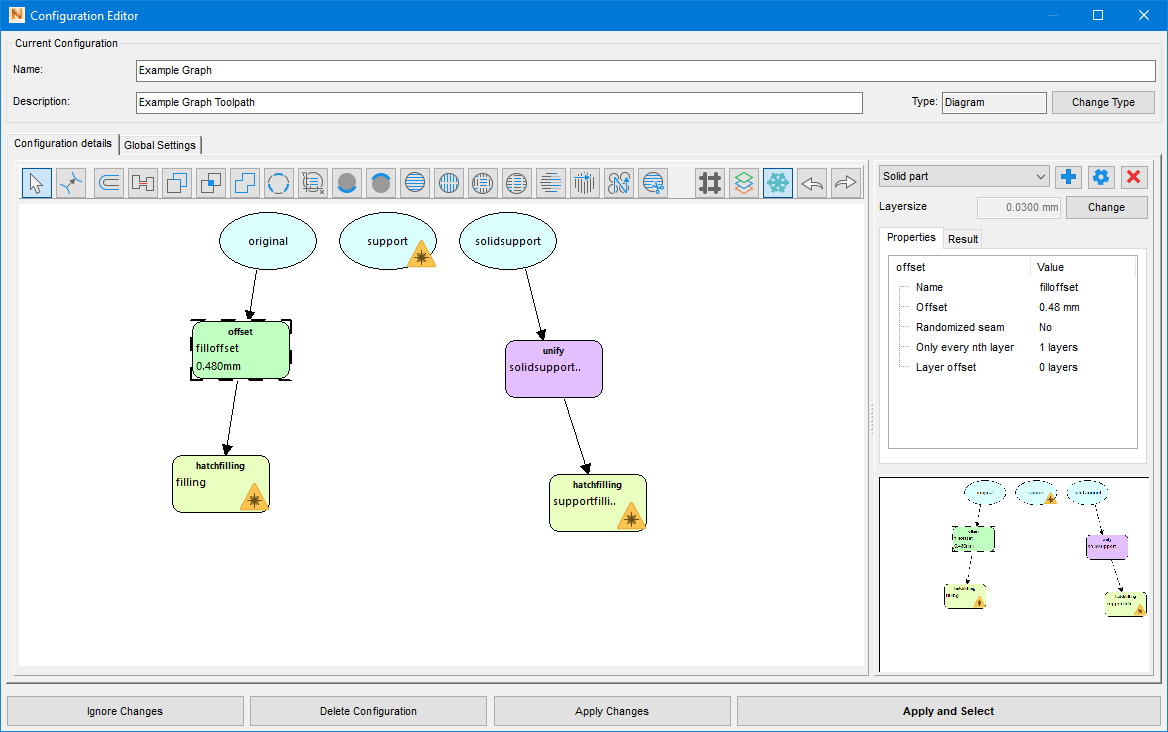
The Example Graph diagram chains basic calculation steps like offset, unify, and hatch filling to create a very simple toolpath for original (part), support, and solid support.
Prerequisites
- A machine of type Autodesk Generic MPBF defined in My Machines and loaded and selected in the project tree.
Steps
-
Creating the configuration
- In the context view, click .
- In the Configuration Editor dialog, click New Configuration.
- In the opening template selection, select Inconel 625 Defaults (30µm, 100W) and click Create Configuration.
- Change the name from New configuration (Inconel 625 Defaults (30µm, 100W)) to Example configuration.
- Click and confirm the change.
-
Editing the configuration
- In the Configuration details tab, select all elements and hit Delete.
- In the bar of icons, click offset and click into the drawing area to place an offset action.
- In the Properties tab to the right, adjust Name to fill offset and Offset to 0.480.
Proceed similarly for the actions unify and hatchfilling (twice) to create the configuration as shown in the image.
-
Finalizing the configuration
- In the bar of icons, click
 Create connection.
- For each connection, click the source action first, then the target action next. For example, click original first, then offset second.
- Right-click both hatchfilling actions and choose Set as result for each from their context menus.
- In the bar of icons, click
-
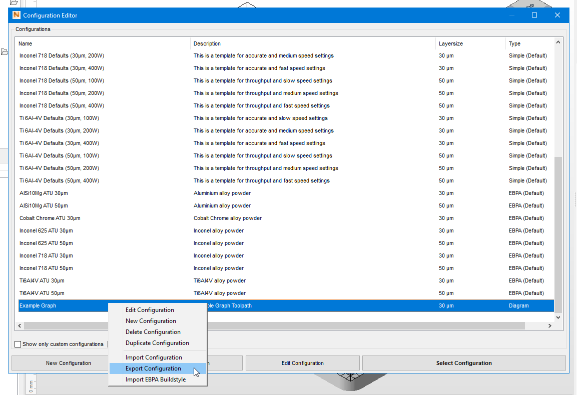
Saving and exporting
- Click Apply Changes.
- Back in the list of configurations, right-click the Example configuration you just created and choose Export configuration.
- Select a saving location and save the file as Example Graph.toolpathxml.