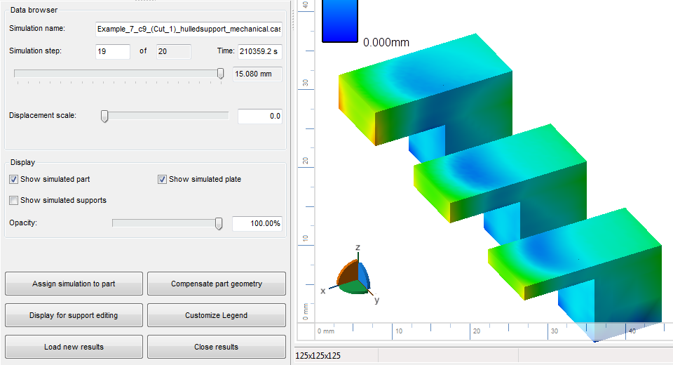
Show results provided by Autodesk® Netfabb® Local Simulation together with the parts used in the simulation
Loading simulation results into Netfabb allows superimposing them to adjust critical sections, such as support structures which were shown to have insufficient strength. It also allows generating compensated geometry directly in Netfabb.
- In
Netfabb, choose
Analyze >
 Load Netfabb Simulation Results.
- Navigate to the folder created by Autodesk® Simulation Utility for Netfabb® during set-up and run of the simulation.
- Find the file that ends with _MECHANICAL.SIMRESULT and click Open.
Load simulation results into Netfabb in preparation for applying adjustments based on information learned from them.
Application of Simulation Results
Simulation results are applied either as a visual aid, or used as the base for processing calculations. For some applications it is necessary to make a choice of the right simulated step, for others it does not matter which simulation step is currently selected as the selection will be made automatically. At any rate, you have the choice between Displacement Magnitude, Displacement along any of the cardinal axes, and the von Mises Stress, from the beginning to the end of the simulation.
To begin, select the relevant dataset in the project tree. Then choose from the context menu based on the application:
- Assign simulation to part – Generate a new part with color information, visualizing the simulation results: From a part selection, find the original part used for the simulation. The part is copied and has color information added to the copy's triangle net which reflects the color-grading of the selected distortion result at the chosen simulation step. The new part is then added to the project tree.
- Display for support editing – Makes simulation information visible and usable for support generation and modification: From a part selection, find the original part used for the simulation. In the support module loaded on the selected part, you then, on the
View tab, have the option to toggle and adjust the display of the overlay. This, too, uses the information of the currently selected simulation step.
Note: Note that, to be eligible for this, the part must have the support module loaded on it, otherwise it is not available in the list of selectable part. It is not enough for it to have parametric support attached. Also, the position of the part on the simulated platform must match, otherwise the display will be misaligned.
As a next step here you could generate a density map for adjusting support structure strength.
- Compensate part geometry – Apply simulation results to distort a mesh or a parametric part: This can be used to artificially emphasize, or to compensate for, a part's distortion resulting from the thermal effects during the additive process. With Simulation increment you specify which simulation step to be applied: Here, the currently selected step is ignored. Instead, you may pick steps from a dropdown that are equivalent to still connected to build platform, separated from platform but with support still attached", and part only with support removed. Compensation magnifier sets the direction and multiplier for the distortion: For example, a value of -1 will compensate for the current distortion against the original geometry. Finally, to replicate the granularity of the simulation result, any triangles significantly larger than this in the original should be subdivided to allow for suitable displacement, otherwise any local distortion can only be applied averaged. Mesh target edge length provides a guideline for Netfabb during the subdivision.