Simulation Utility can simulate a part build, and then create a redesigned part that compensates for the anticipated distortion of the build process. If the part is correctly compensated, it will distort into the desired finished dimensions, and a simulation should demonstrate this.
This exercise makes use of one of the sample files for the Simulation Utility tutorials, available on the Download Page. An overview of the exercise is as follows:
- Import an STL file into Simulation Utility, run a simulation, and examine the distortion.
- Create a compensated STL file, and run it through another simulation.
- In Netfabb, run a mesh comparison study with the initial STL file and the STL exported from the compensated simulation.
To run the initial simulation
- In
Netfabb, open the file
Example_5.stl.
- Using all the default settings, click Solve
 on the Home tab to run a simulation.
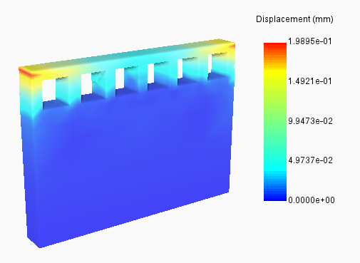
Maximum displacement results are shown for the part, still attached to the build plate. Note that distortion is concentrated at the upper, outer corners.
To create and test the compensated STL file
- On the Results tab for the initial simulation, click Warped STL
 .
.
- In the
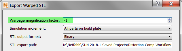
Export Warped STL dialog box, set the
Warpage Magnification Factor to
-1.
- Export the compensated STL file, then open the project folder where the file is saved. Note that the name of the new STL file ends in _warp-1.stl.
- From the Simulation menu, create a new Simulation project and import the compensated STL file, <part name>_tivus_warp-1.stl.
- Run a simulation with this file, and again examine the maximum displacement results.
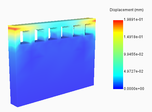
The results look very similar to the original simulation in the magnitude and location of displacement, but the part looks much closer to the originally intended geometry.
- On the Results tab, click Warped STL, and set the
Warpage Magnification Factor to
1.
This setting will export an STL file that shows the predicted distortion of the simulation using the compensated geometry.
- Export the warped STL file, then open the project folder where it is saved. Note that the name of the new STL file ends in _tivus_warp1.stl.
Next, we will use Netfabb to compare the warped STL file from the compensated geometry simulation with the reference geometry, Example_5.stl.
To compare STL meshes
- In
Netfabb, click
and add first
Example_5.stl, then add the warped STL you last exported.
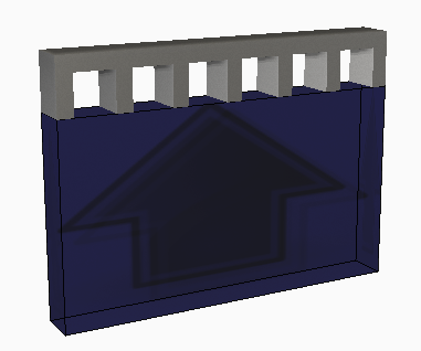
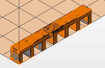
The two files can be superimposed, as shown below.
- Click
.
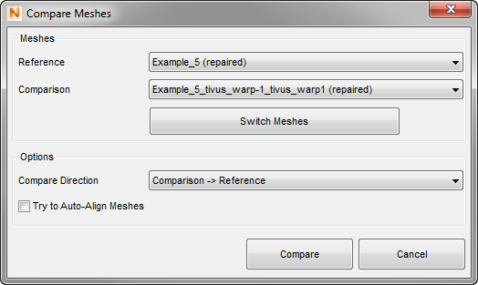
- In the Select Mesh dialog box, use the settings shown above.
- Click Compare.
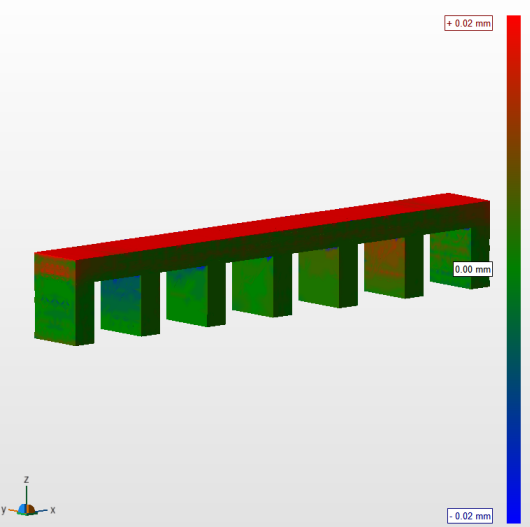
In the analysis results, notice that some nodes in the compensated mesh are farther from the origin (red) and others are closer (blue), but all are within 0.02 mm of the original STL nodes.