For the toolpath calculation there are two main entry point functions which can be implemented by script developers: the buildProcessingGraph entry point function and the makeExposureLayer entry point function. Only one of these functions is allowed to be defined in the main.js file.
In the buildProcessingGraph entry point function, a processing graph with custom processing nodes is configured to generate the toolpath. The makeExposureLayer entry point function is called for each layer of a part and the toolpath calculation for a layer is implemented there.
The generated project implements the buildProcessingGraph entry point function (and not the makeExposureLayer entry point function). The buildProcessingGraph entry point function is particularly suitable for this type of project because it allows a diagram from the graphical toolpath editor to be implemented in script code in a comprehensible manner.
It is challenging to start a new project using the buildProcessingGraph entry point function from scratch, without using a diagram from the graphical toolpath editor as a source. Compared to using makeExposureLayer, the performance of the buildProcessingGraph based toolpath calculation is lower in many cases.
Resulting ATU project
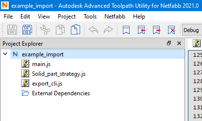
In this example, the generated project contains three files: the mandatory main.js file, CLI exporter code export_cli.js, and code for the actual toolpath calculation Solid_part_strategy.js.
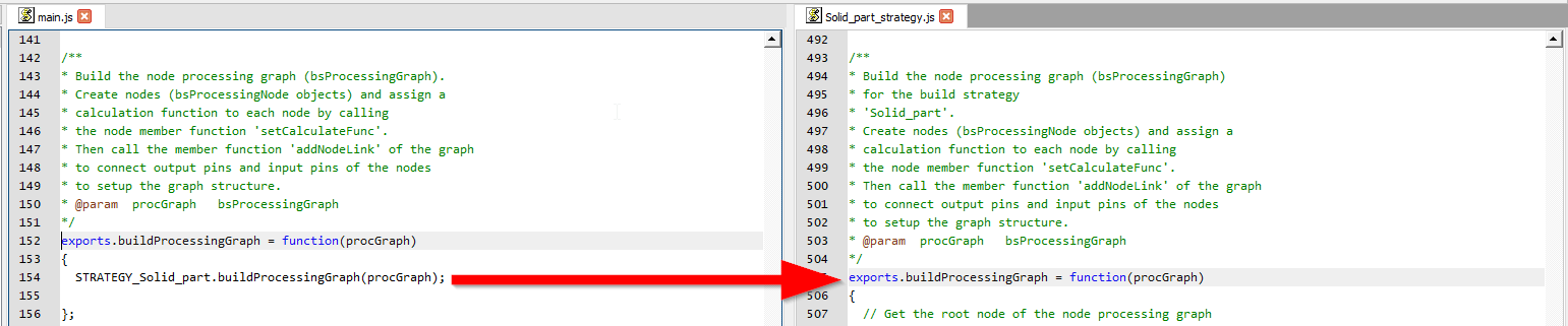
The buildProcessingGraph entry point function in the main.js calls the buildProcessingGraph function of the STRATEGY_Solid_part script module. There could be more than one build strategy defined in the diagram configuration (toolpathxml) but in this example there is just one build strategy Solid part.
The buildProcessingGraph function
The job of the buildProcessingGraph function is to fill the given processing graph (a bsProcessingGraph object) with processing nodes (bsProcessingNode objects) where nodes are connected by node links.
Consequently, the function first creates the bsProcessingNode objects and each object is given a name. The bsProcessingNode object needs a calculation function which transforms the input model(s) of the node into the output model(s). A node without a calculation function is not usable. When a diagram configuration (toolpathxml) is imported, calculation functions are generated, and the associated calculation function is assigned to each node by calling the member function setCalculateFunc of the node.

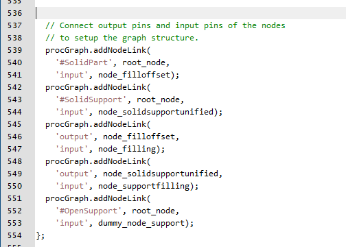
After the creation of the processing nodes, the addNodeLink member function of the given processing graph is called multiple times to connect the nodes. Nodes have input- and output-pins where other nodes could be connected. These node-pins are providing or receiving layer models (bsModel) where the name of the pin is equal to the model name. The processing graph always contains a root node with the output pins #SolidPart, #SolidSupport, #OpenPart, #OpenSupport. Pin names starting with '#' are unique built-in names. Custom node pins are not allowed to be named with a leading '#'.
Node calculation functions
The calculation function of a node is a custom function which transforms the input model(s) into the output model(s). It is the place where the actual work is done.
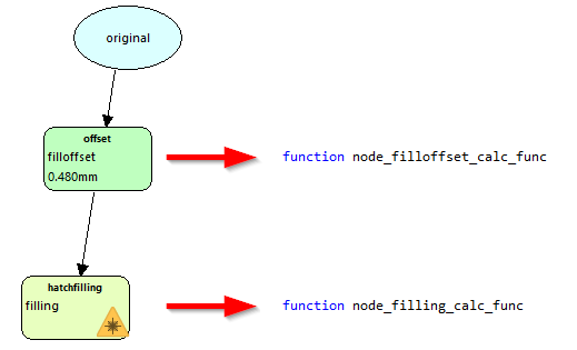
In the generated code there is a direct mapping from a node of the diagram configuration to a processing node with a calculation function.
For example, the STRATEGY_Solid_part script module contains the function node_fillofset_calc_func which is the calculation function for the node filloffset. The function node_filling_calc_func is the calculation function for the node filling.
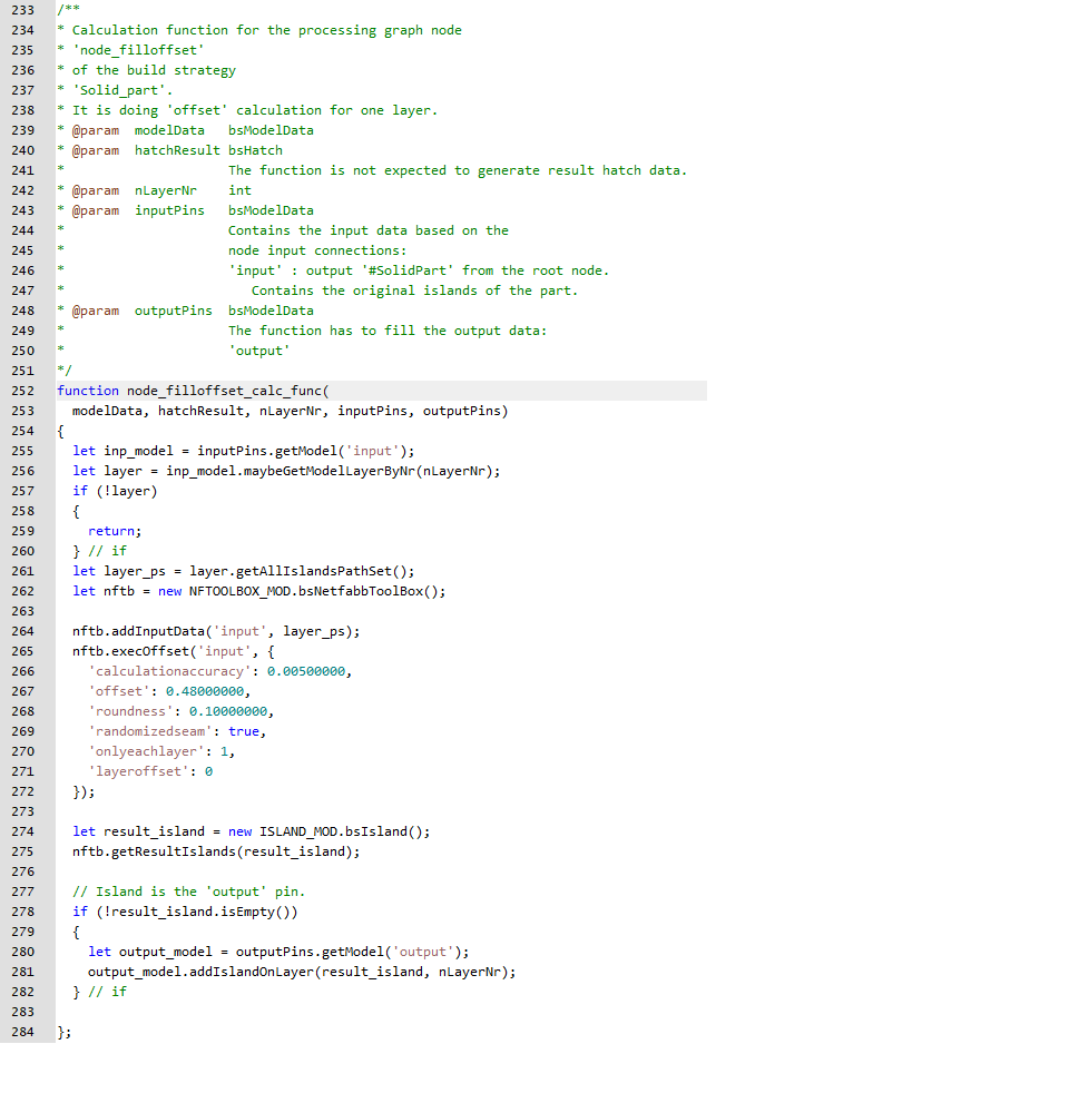
The function node_fillofset_calc_func takes as input (input model input) the original islands of the part. The configuration of the input happens in the buildProcessingGraph function, where the output #SolidPart of the root node was set as input for node filloffset). First step of the function is to get the input model of the inputPins argument object (a bsModelData object). Then, a bsPathSet object of all islands of the input model of the current layer (layer number nLayerNr) is created and given to a bsNetfabbToolbox object for offset calculation. The result of the offset calculation is then written to the current layer of output model of the outputPins argument object (a bsModelData object).
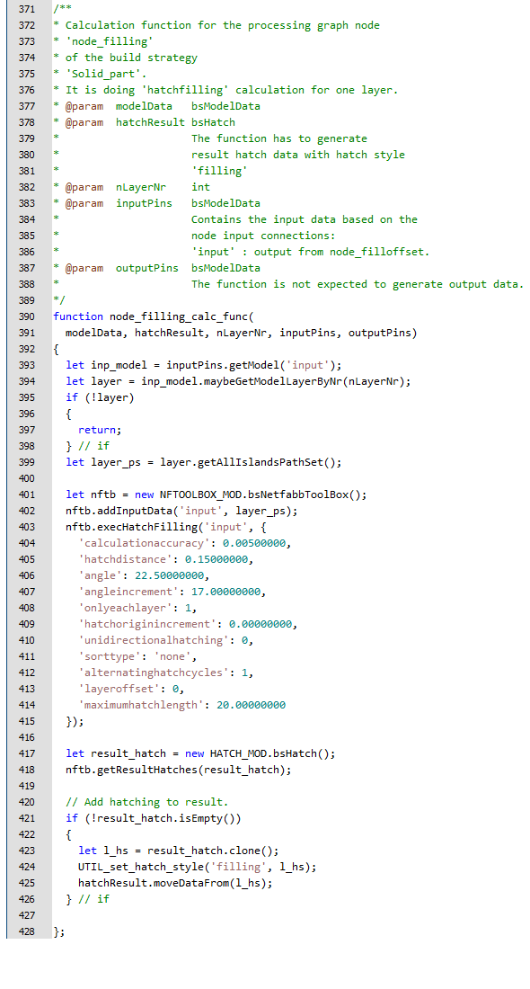
Continuing the route in the diagram, the function node_filling_calc_func accepts as input model the output model of the function node_fillofset_calc_func (as configured in the buildProcessingGraph function).
The node_filling_calc_func function creates a bsPathSet object of all islands of the input model of the current layer and gives it to a bsNetfabbToolbox object to create the hatching. The hatching data is then moved to the result bsHatch object hatchResult.