Introduction
In this exercise, we will simulate a ball dropping from 12 inches onto a steel plate and rebounding back up into the air. This is an example of a nonlinear transient analysis. It requires both dynamic and nonlinear setup steps. Autodesk Inventor Nastran solves both domains essentially simultaneously.
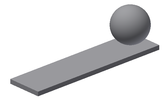
Even though we are dropping the ball from 12 inches, we will position the ball in the model so that it is almost touching the plate. This is done for solution efficiency. We will assign an initial velocity to the ball of 96.3 in/s, which is the velocity the ball would reach after dropping 12 inches.
V = SQRT(2 x G x d) = SQRT(2 x 386.4 x 12) = 96.3 in/s
Note that we are assuming that the difference in velocity from the initial position to the actual contact is negligible.
The other consideration is to determine roughly how long it will take the ball to traverse the distance in the model (0.06 inches) at a velocity of 96.3 in/s.
T = d/V = 0.06 / 96.3 = 0.0006 s
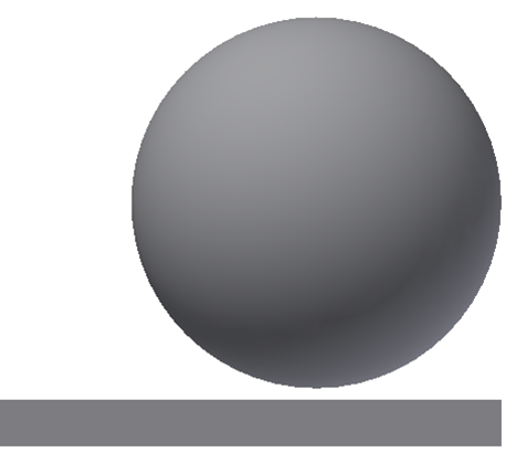
This is necessary to determine a time step size that is small enough to adequately resolve the impact. After the impact, we can increase the time step in a second subcase.
1. Open the Model and Start the Autodesk Inventor Nastran Environment
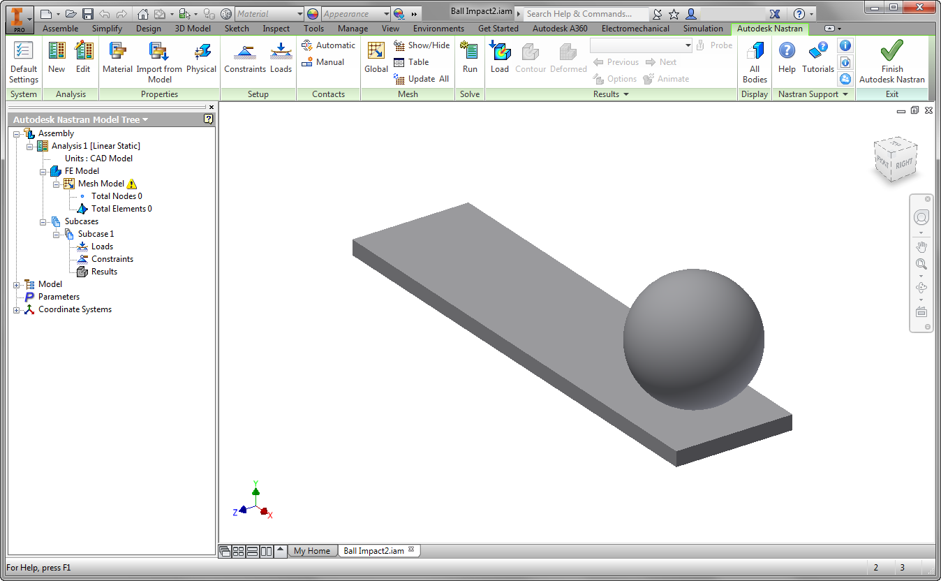
Start Autodesk Inventor, and open Ball Impact2.iam from the Section 17 - Ball Impact sub-folder of your training exercises folder.From the Environments ribbon tab, click Autodesk Inventor Nastran. In the Model tree, expand Idealizations. If any Idealizations are already defined, like Solids 1 and 2 below, right-click , to ensure that no unwanted materials can participate in the analysis.

You should see this:
2. Change the Analysis Type
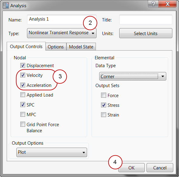
- From the Analysis tree, right-click .
- On the Analysis dialog, set the Type to Nonlinear Transient Response.
- Enable both Velocity and Acceleration Nodal Output Control types.
- Click OK.
3. Define the Property and Material
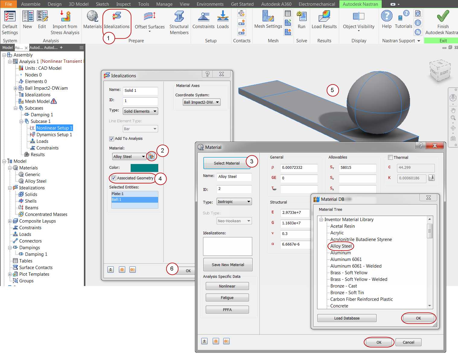
- Click Idealizations from the ribbon.
- Click the New Material icon.
- On the Material dialog, click Select Material. Expand the Inventor Material Library, and select Alloy Steel. Click OK and OK to close both dialogs.
- In the Idealizations dialog, check the Associated Geometry box.
- Select both parts.
- Click OK.
4. Constrain the Plate
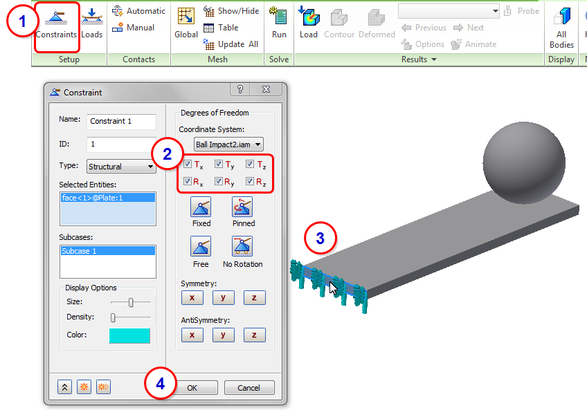
- Click Constraints from the ribbon.
- Make sure all degrees of freedom are constrained (checked).
- Select the end of the plate.
- Click OK.
5. Constrain the Ball
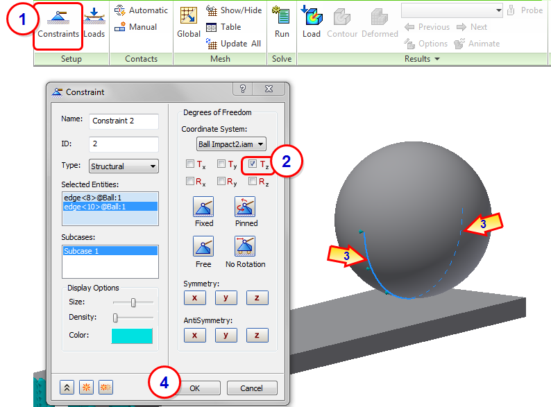
This constraint ensures the ball does not bounce sideways as a result of element face angles. Although not required for the analysis, it ensures that we get the response in the expected direction.
- Click Constraints from the ribbon.
- Uncheck all degrees of freedom except Tz.
- Select the two edges on the lower half of the ball that run parallel to the long dimension of the plate.
- Click OK.
6. Define the Initial Velocity
This value defines the velocity of the ball at the beginning of the analysis. This is the value we computed in the introduction, and is the ball's velocity after having been dropped from 12 inches above the plate.
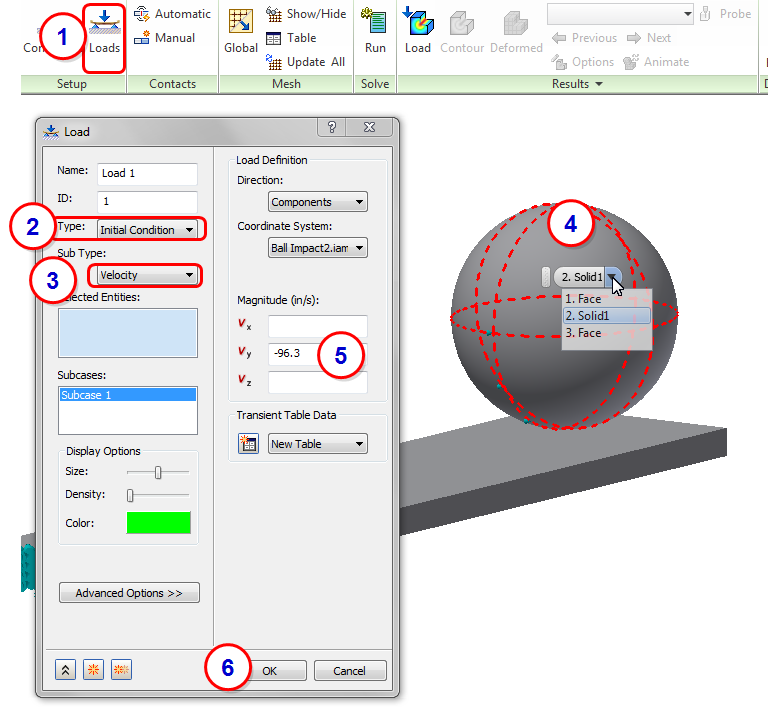
- Click Loads from the ribbon.
- Set the Type to Initial Condition.
- Set the Sub Type to Velocity.
- Select the solid ball. An easy way to do this is to hover over one of the surfaces of ball (but don't click it). When the Select Other menu appears, expand it, and select Solid1.
- Enter -96.3 in/s for Vy.
- Click OK.
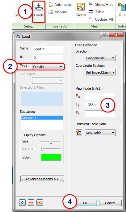
7. Enable Gravity
- Click Loads from the ribbon.
- Set the Type to Gravity.
- Enter -386.4 in/s2 for Fy.
- Click OK.
Note that this is the only load that persists throughout the analysis. The initial condition only applies at the beginning of the analysis.
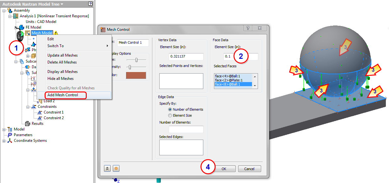
8. Assign Mesh Control to the Contacting Faces
- From the Analysis tree, right-click .
- Enter an Element Size of 0.1 for the Face Data, and click in the Selected Faces field to activate it.
- Select the four bottom surfaces of the ball and the split face on the end of the beam.
- Click OK.
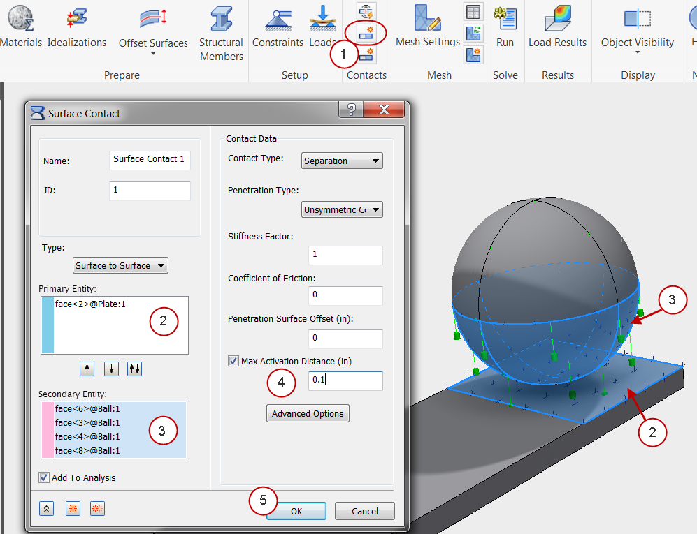
9. Define Contact
- Click Manual from the Contacts panel in the ribbon.
- Click in the Primary Entity field, and select the surface on the plate.
- Click in the Secondary Entity field, and select the four bottom surfaces of the ball.
- Enter 0.1 as the Max Activation Distance.
- Click OK.
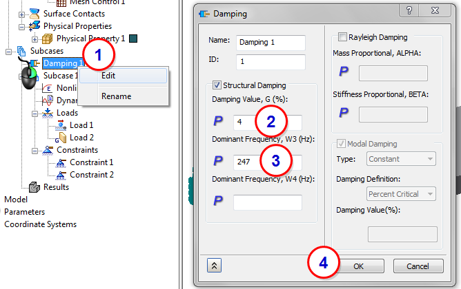
10. Define Damping
For this model, we will choose the first bending mode as the Dominant Frequency.
- Right-click on Damping 1 from the Analysis tree, and click Edit.
- Enter 4 as the Damping Value, G. (This value represents 2% damping entered as 2X.)
- Enter 247 as the Dominant Frequency, W3.
- Click OK.
11. Define the First Subcase
We will use two subcases to control the time step size. In the first subcase, we will assign a very small time step to capture the descent and impact of the ball. In the next step, we will create a second subcase with a larger time step to capture the motion of the ball as it rebounds off of the plate.
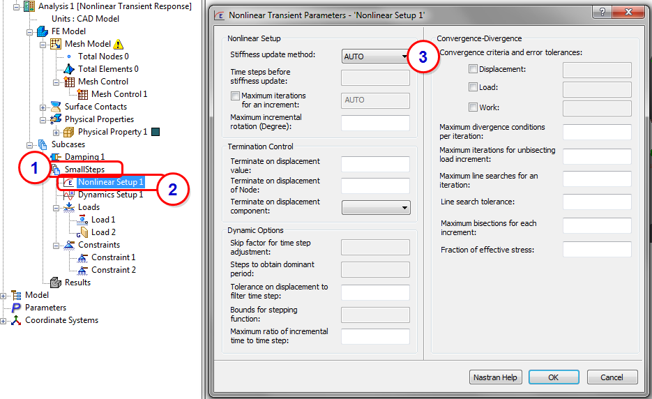
- Right-click on Subcase 1, and click Rename. Enter the name SmallSteps.
- Right-click on Nonlinear Setup 1, and click Edit.
- On the Nonlinear Transient Parameters dialog, select AUTO as the Stiffness update method. Click OK.
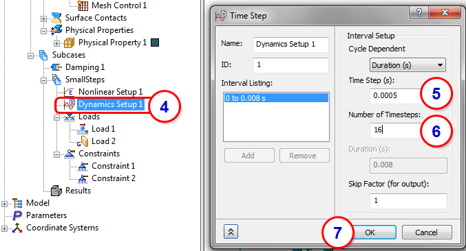
- Right-click on Dynamics Setup 1, and click Edit.
- Enter 0.0005 as the Time Step.
- Enter 16 as the Number of Timesteps.
- Click OK.
12. Define the Second Subcase
We create the second subcase by copying the first subcase and modifying the time step parameters.
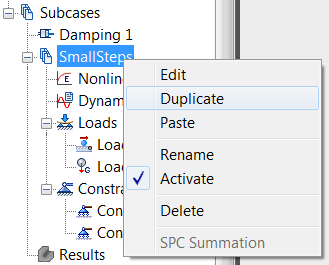
- Right-click on the SmallSteps subcase, and click Duplicate.
- Click on the new subcase, SmallSteps - Copy, and rename it to BigSteps.
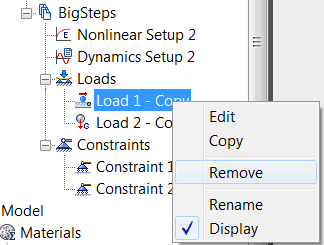
- Right-click on the initial condition load, Load 1 - Copy, and click Remove.
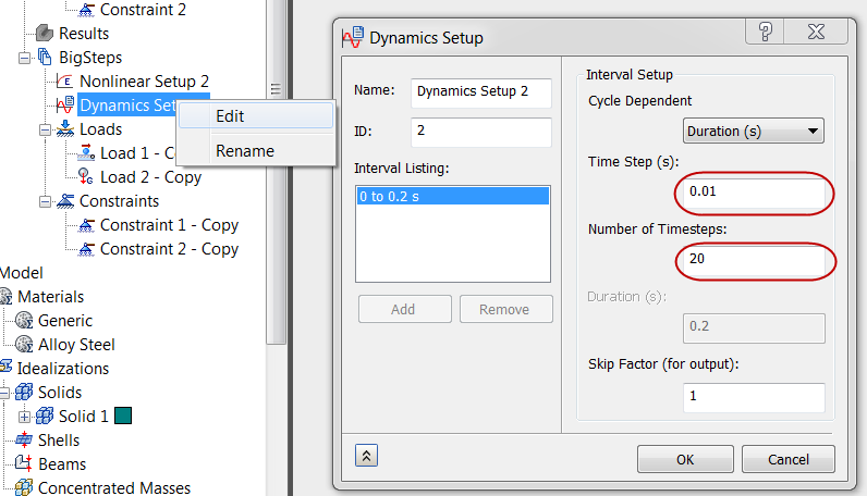
- Right-click on Dynamics Setup 2, and click Edit. Change the Time Step to 0.01, and the Number of Timesteps to 20. Click OK.
13. Mesh the Model and Run
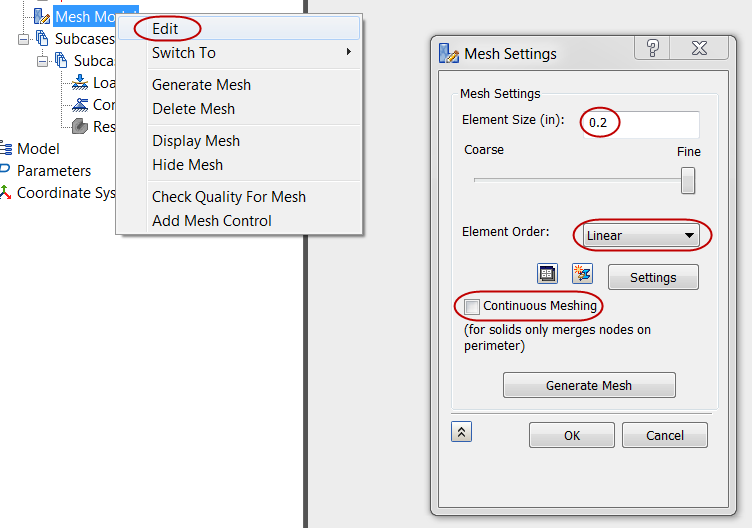
- Right-click on Mesh Model, and click Edit.
- Change the Element Size to 0.2.
- Set the Element Order to Linear.
- Uncheck Continuous Meshing.
- Click OK to close the Mesh Settings dialog box and generate the mesh.
- Run the analysis by clicking Run from the ribbon.
14. Review the Time-History of Displacement
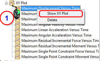
- From the XY Plot branch, right-click on Maximum Displacement Versus Time, and click Show XY Plot.
You should see this:
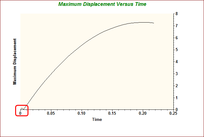
The area circled in red is the initial bounce, and was computed with the smaller time step in the first subcase.
15. View a Multiset Animation
- Right-click on Results, and select Multiset Animation Settings.
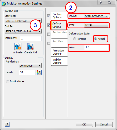
- Click the Deform Options tab. Set the Vector to Displacement, and the Type to Total. Change the Deformation Scale to Actual, and specify a Value of 1.0.
- Set the Start Set to STEP 1, and the End Set to STEP 22.
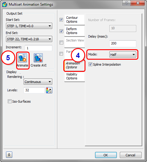
- Click the Animation Options tab, and change the Mode to Half.
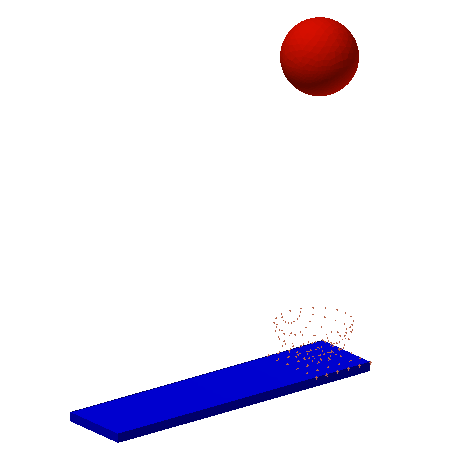
- Click Animate and then OK to close the dialog box.
- To stop the animation, right-click Results and uncheck Multiset Animate.
Summary
In this exercise, we combined both dynamics and nonlinear responses to produce a nonlinear transient analysis. These types of analyses can be complex, but they are some of the most exciting solution types in FEA.
|
Previous Topic: Nonlinear Transient Analysis |
Next Topic: Nonlinear Materials |