Create Material
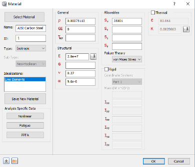
The structure is made from a carbon steel material. With the iLogic commands, we can specify the complete material definition.
- Copy the following text:
strCmdForNewMaterial = "<NewMaterial Name=""AISI Carbon Steel "" ID=""2"" Type=""0"" IdealisationIDList="""" DENS=""8027.2[kg/m^3]"" GE=""0.0"" REFT=""[K]"" EX=""193050000000.0[Pa]"" GXY="""" NUXY=""0.27"" ALPX=""0.00001728[/K]"" SIGXT=""241320000.0[Pa]"" SIGXC=""[Pa]"" SIGYLD=""[Pa]"" C=""900.0[J/(kg K)]"" KX=""221.78[W/m K]"" FailureTheory_Type=""1"" HasConductivityTable=""0"" HasYoungsModulusTable=""0"" NonLinearType=""0"" SN_B="""" SN_Smu=""[Pa]"" SN_N0="""" SN_KF="""" SN_Be="""" SN_Se=""[Pa]"" EN_SF="""" EN_EF="""" EN_B="""" EN_C="""" HasPPFA=""0""/>"
- These commands are equivalent to creating a material through the user interface.
- Paste the text below the existing commands in the Edit Rule dialog.
- Press the Enter or Return key twice to jump down to a new line.
Create Line Element Idealization
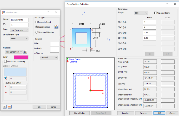
For this simulation, we’ll apply line elements to our structure. To do so, we’ll create a new line type idealization.
- Copy the following text:
strCmdFornewIdealization = "<NewIdealization Name=""Line Elements"" ID=""1"" Type=""0"" LineElementType=""1"" InputType=""2"" ShapeType=""12"" HasTapperedBeam=""0"" DIM1_EndA=""0.1016[m]"" DIM2_EndA=""0.1016[m]"" DIM3_EndA=""0.00635[m]"" DIM4_EndA=""0.00635[m]"" HasAssociatedGeo=""0"" PreLoadType=""0"" OffsetType=""0"" AddToFEModel=""1"" Color=""11087083"" CoodinateSystemID=""0"" MaterialID=""2"" EntitiesCount=""0""/>"
Type = 0 denotes the use of line elements. LineElementType = 1 denotes the use of beam elements. InputType = 2 and ShapeType = 12 denote the use of box shaped cross-sections for the line elements.
These commands are equivalent to defining the idealization through the user interface.
- Paste the text below the existing commands in the Edit Rule dialog.
- Press the Enter or Return key twice to jump down to a new line.
Create Mesh
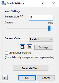
The mesh is defined using two commands. The <MeshModel> command to define the properties of the mesh and the <GenerateMesh> command to produce the mesh.
- Copy the following text:
strCmdForMeshModel = "<MeshModel AnalysisID=""1"" HasContiniousMeshing=""0"" HasMeshTable=""0"" ElementSize=""0.1016[m]"" Tolerance=""0.0000000203[m]"" ElementOrder=""3"" HasRefinmentRatio=""1"" RefinmentRatio="""" MinTriangleAngle=""[rad]"" MaxTriangleAngle=""[rad]"" MaxElementGrowthRate="""" SuppressShortFeature="""" MinFeatureAngle=""[rad]"" HasProjectMidsideNodes=""0""/>"

strCmdForMesh = "<GenerateMesh/>"
Element Order = 3 denotes the use of parabolic elements.
These commands are equivalent to defining the mesh with the user interface.
- Paste the text below the existing commands in the Edit Rule dialog.
- Press the Enter or Return key twice to jump down to a new line.