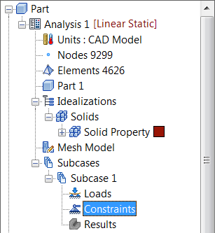
- The square back face of the bracket is fixed. Use the View Cube to orient the part so that you have a clear view of the back face. Right-click on
Constraints under
Subcase 1 and select
New.
 All the entities that you will be creating will also appear in Model Entity list. This list will expand as the modeling progresses. The Model Entity list provides a means of easily applying entities to other subcases as well.
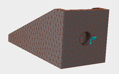
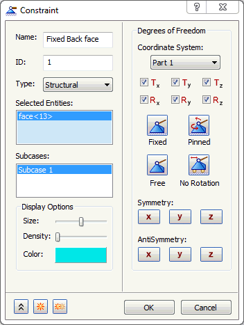
- When the
Constraint dialog appears, select the back face.
- Type
Fixed Back Face
for the
Name of the constraint.
Note: In the Display Options section of the Constraint dialog, you can adjust the size, number, and color of the constraint symbols that appear in the part display.
- Be sure that
Subcase 1 is selected in the
Subcases list, and then click
OK. This will automatically add the constraint to
Subcase 1.
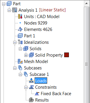
- Right-click on
Loads under
Subcase 1 and choose
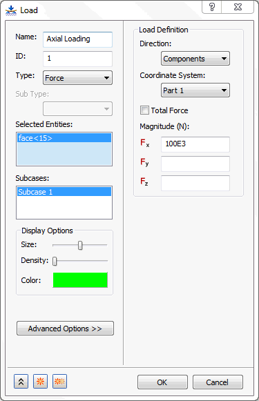
New. In this subcase, the load is a 100 KN force applied to the first bolt hole of the bracket in the positive x-direction.
- Enter Axial Loading in the Name field.
- Select the interior surface of the first bolt hole farthest from the back face and type in
100E3 for
Fx.
Note: In the Display Options section of the Load dialog, you can adjust the size, number, and color of the load symbols that appear in the part display.
- Be sure that
Subcase 1 below the
Subcases list is selected.
- Then click
OK.
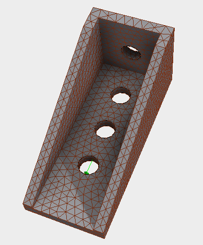
You can also drag-and-drop different entities in the tree view. For example, the
Axial Loading
load and the
Fixed Back Face
constraint can be dropped on top of the
Subcase 1 name. The model should look as shown below.
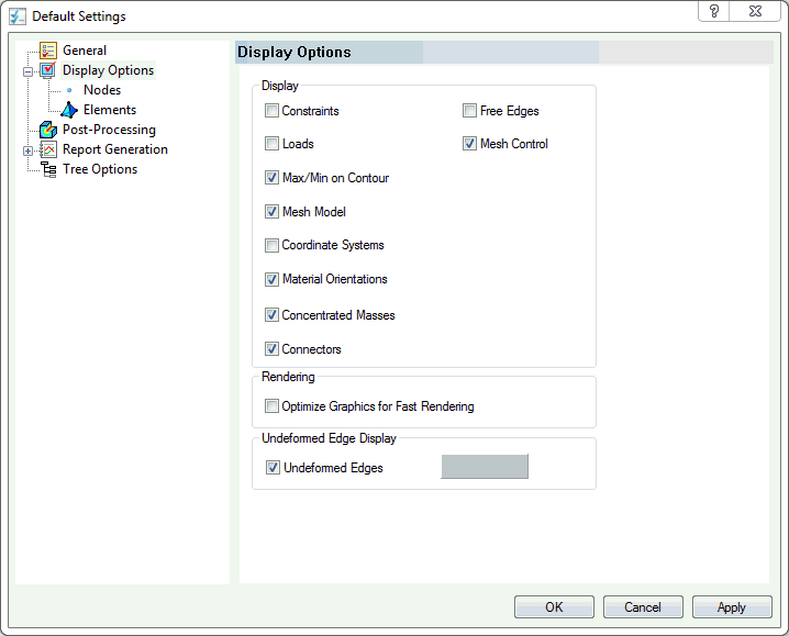
 You can hide the loads and constraints.
Click on
Autodesk Nastran menu tab on the top of the CAD interface, and then choose
Default Settings under the
System panel on the ribbon. Then click
Display Options and uncheck the
Loads and
Constraints checkboxes. They can also be hidden by right-clicking on the
Loads or
Constraints within the
Subcases section in the tree and checking
Hide All.
You can hide the loads and constraints.
Click on
Autodesk Nastran menu tab on the top of the CAD interface, and then choose
Default Settings under the
System panel on the ribbon. Then click
Display Options and uncheck the
Loads and
Constraints checkboxes. They can also be hidden by right-clicking on the
Loads or
Constraints within the
Subcases section in the tree and checking
Hide All.
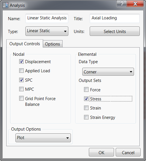
- In the tree view, right-click on Analysis 1 and select Edit.
- Type Linear Static Analysis for Name, type Axial Loading for Title, and select Linear Static for the analysis Type.
- Ensure that
Displacement is checked under
Nodal Output Control and
Stress is checked under
Elemental Output Sets, then click
OK.
Later in this tutorial, another subcase will be added to the model with a vertical load. Save the model at this point.