You will use the temperature distribution from the nonlinear steady state heat transfer analysis as a load for a linear static analysis. You will then be able to see the stresses experienced by the part due to thermal expansion. The model will have fixed constraints at the bolt holes, and will be allowed to slide along the surfaces on the flanges facing away from the tubes.
Set Up the Analysis
- In the tree view, right-click on Manifold Analysis, and choose Duplicate. This will create a copy of the analysis with the name as Manifold Analysis - Copy.
- Now, Manifold Analysis - Copy tree is in active mode. Under Subcases left-click on Subcase 1 to select the name, and rename it to Subcase 2. Remove the Initial Temperature load from Subcase 2 as it is not required for a thermal stress analysis.
- Right-click on Manifold Analysis - Copy and choose Edit.
- Enter
Thermal Stress
for
Name, and type
Thermal Stress Analysis
for
Title. Change the analysis
Type to
Linear Static from the drop-down menu.
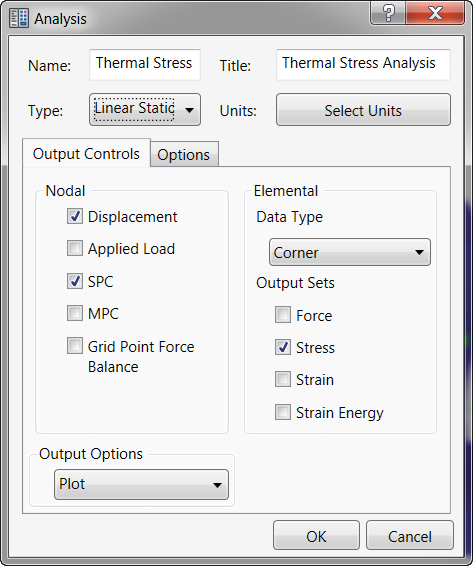
- Click OK.
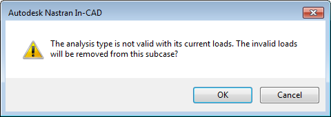
- All thermal loads will be removed from the analysis as they are not related to the linear static analysis. However, the Initial Temperature had to be removed manually.
- Click
OK in the following message window.
Apply Loads and Constraints
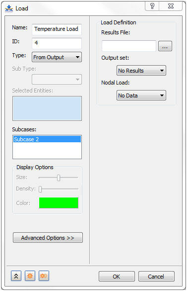
- Right-click on Loads under Subcase 2 and select New.
- Change the Name to Temperature Load.
- Change the Type to From Output.
- In the
Load Definition section click on the browse button for the
Results File. Navigate to the location of the FNO file, which was generated after running the Nonlinear Steady State Heat Transfer Analysis. For example,
C:\Users\Public\Public Documents\Autodesk\Inventor Nastran 2023\Tutorial\en-us\Inventor 2023\Thermal Stress Manifold\In-CAD\FEA folder. Then open the FNO file.
- The
Load dialog shows that
INCR 1, LOAD=1.0 is selected as the
Output Set and
TEMPERATURE is selected for the
Nodal Load, as shown below.
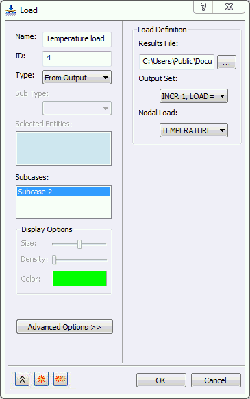
- Click
OK to complete the definition of temperature load from output.
- In the tree view, right-click on Constraints and select New.
- Select the bolt hole surfaces highlighted in blue in the image shown below.
- Rename the constraint to
Structural Constraints.
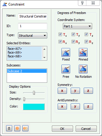
- Accept the default settings. Be sure that
Subcase 2 is highlighted, and then click
 New button to define another constraint.
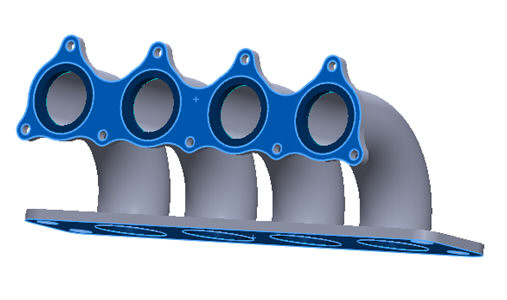
- Rename
Constraint 2 as
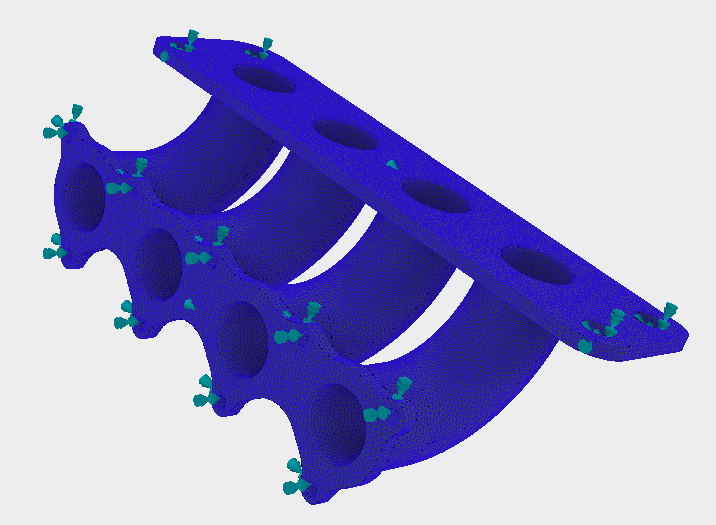
Sliding Surfaces. Select the surface on both of the flanges facing away from the tubes highlighted in blue in the image shown below.
- Uncheck all the degrees of freedom except
Tx. This will allow the nodes on the surface to slide about the plane they are in, but will not allow it to penetrate it.
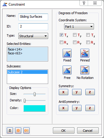
- Make sure that Subcase 2 is highlighted, and then click OK to close the dialog.
- The final model should look as shown below.
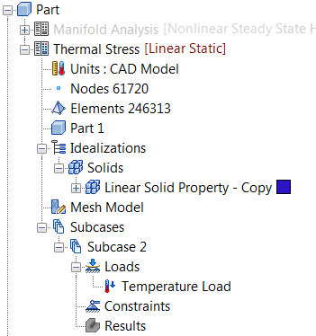
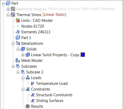
- After defining all entities, the final tree view should look as shown below.
Run the Analysis and Post-Process the Results
- Save the model at this point.
- Right-click on Thermal Stress Analysis in the tree view and select Solve in Nastran.
- Autodesk Nastran solves the model and displays the progress in the Autodesk Nastran Output window inside Inventor Nastran.
- When you see the dialog "Nastran Solution Complete", click OK to load the results into Inventor Nastran.
- After the solution is completed, Inventor Nastran loads the results.
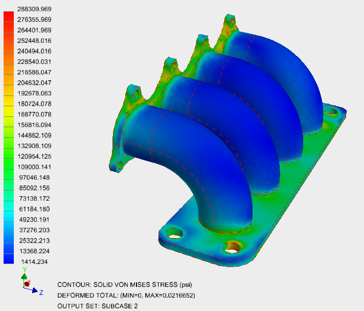
- Under Results in the tree view, right-click on von Mises and select Edit.
- Uncheck
Max/Min Markers under
Display Options. On the
Deform Options tab, select
Actual to view the actual displacements. On the
Contour Options tab, ensure that
Result Data is set to
Stress, and Type is
SOLID VON MISES STRESS. On the
Visibility Options tab, select
Hide All.
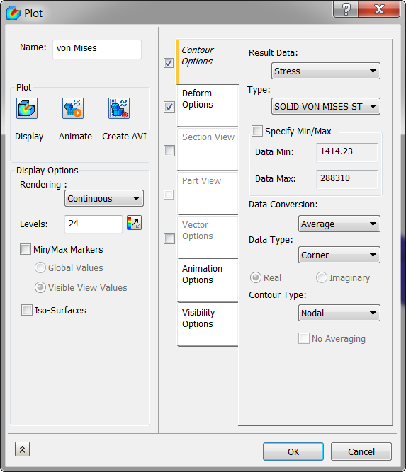
- Click on
Display. The results should look as shown below.
This concludes Heat Transfer and Thermal Stress Analysis of An Exhaust Manifold.
The following summarizes the main topics covered:
- How to create thermal boundary conditions – convection and heat flux.
- How to set up thermal loads with the output from a previous analysis to run a thermal stress analysis.
- How to post-process thermal stress results.