Create Material
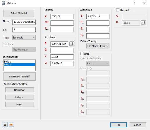
The bracket is made from a stainless steel material. With the iLogic commands, we can specify the complete material definition.
- Copy the following text:
strCmdForNewMaterial = "<NewMaterial Name=""16-25-6 Stainless Steel"" ID=""2"" Type=""0"" IdealisationIDList="""" DENS=""8504.9[kg/m^3]"" GE="""" REFT=""[K]"" EX=""19443000000[Pa]"" GXY="""" NUXY=""0.295"" ALPX=""0.00001692[/K]"" SIGXT=""77221000[Pa]"" SIGXC="""" SIGYLD="""" C="""" KX=""25.85[W/m K]"" FailureTheory_Type=""1"" HasConductivityTable=""0"" HasYoungsModulusTable=""0"" NonLinearType=""0"" SN_B="""" SN_Smu=""[Pa]"" SN_N0="""" SN_KF="""" SN_Be="""" SN_Se=""[Pa]"" EN_SF="""" EN_EF="""" EN_B="""" EN_C="""" HasPPFA=""0""/>"
These commands are equivalent to creating a material through the user interface.
- Paste the text below the existing commands in the Edit Rule dialog.
- Press the Enter or Return key twice to jump down to a new line.
Create Solid Element Idealization
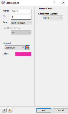
For this simulation, we’ll apply solid elements to our bracket. To do so, we’ll create a new solid type idealization.
- Copy the following text:
strCmdForNewIdealization = "<NewIdealization Name=""Solid 1"" ID=""1"" Type=""2"" AddToFEModel=""1"" Color=""11087083"" CoodinateSystemID=""0"" MaterialID=""2"" EntitiesCount=""0""/>"
Type = 2 denotes the use of solid elements.
These commands are equivalent to defining the idealization through the user interface.
- Paste the text below the existing commands in the Edit Rule dialog.
- Press the Enter or Return key twice to jump down to a new line.
Create Mesh
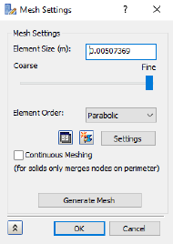
The mesh is defined using two commands. The <MeshModel> command to define the properties of the mesh and the <GenerateMesh> command to produce the mesh.
- Copy the following text:
strCmdForMeshModel = "<MeshModel AnalysisID=""1"" HasContiniousMeshing=""0"" HasMeshTable=""0"" ElementSize=""0.00507369[m]"" Tolerance=""0.000000101474[m]"" ElementOrder=""3"" HasRefinmentRatio=""1"" RefinmentRatio=""0.6"" MinTriangleAngle=""0.349066[rad]"" MaxTriangleAngle=""0.523599[rad]"" MaxElementGrowthRate=""1.5"" SuppressShortFeature=""0.02"" MinFeatureAngle=""0.0349066[rad]"" HasProjectMidsideNodes=""0""/>"

strCmdForMesh = "<GenerateMesh/>"
Element Order = 3 denotes the use of parabolic elements.
These commands are equivalent to defining the mesh properties through the user interface.
- Paste the text below the existing commands in the Edit Rule dialog.
- Press the Enter or Return key twice to jump down to a new line.