Click Object Visibility in the Display panel of the Autodesk Inventor Nastran ribbon tab.

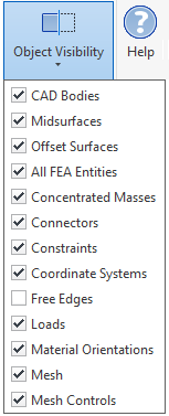
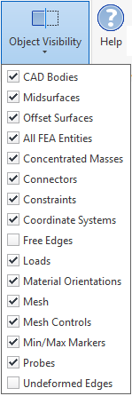
One of the following two lists of options appears, depending upon whether a results contour is currently displayed:
- Results Contour not Displayed:

- Results Contour Currently Displayed:

- All FEA Entities
- This option controls multiple visibility options in a single click. Specifically, it controls visibility of the following objects:
- Concentrated Masses
- Connectors
- Constraints
- Coordinate Systems
- Loads
- Material Orientations
- Mesh
- Mesh Controls
Of course, visibility of each of these objects can also be individually controlled.
- Free Edges
- This option highlights the free edges of shell elements (by overlaying them with a heavy white line). Free edges are those that are not mated with an adjacent shell element edge. This option is useful for finding improperly connected shell elements where faces intersect each other.
- Mesh
- This option controls visibility of the finite element mesh. When displaying results contours, this command is equivalent to the Element Edges option within the Visibility Options tab of the Plot and Multiset Animation Settings dialogs.
- Min/Max Markers
- This option controls visibility of the minimum and maximum results markers, and is only available and applicable when a results contour is displayed. It does not control the visibility of any Probes that you add to the model.
- Probes
- This option controls visibility of anchored probes that you have added to a model, and is only available and applicable when a results contour is displayed. It does not control the visibility of the Min/Max Markers.
- Undeformed Edges
- When viewing a deformed results contour, this option displays dashed lines representing the original (undisplaced) locations of the part edges. By default, the dashed lines are red, but you can choose any desired color within the Default Settings dialog.
The remaining items in the Object Visibility list are self-explanatory.