The Laminate option allows you to define a composite laminate property. Click on the New Laminate button in the Idealizations dialog; or right click Composit Layups\Laminates in the model tree and choose New from the context menu. The Laminate dialog opens.
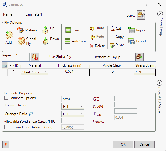
- Ply Options allow you to:
- Add: Add the ply.
- Material: Define a new material.
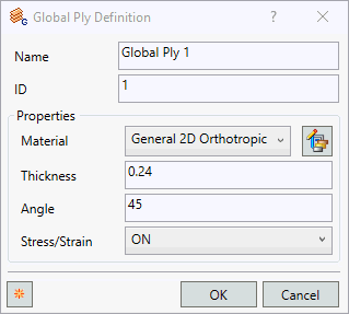
- Global Ply: Define the global ply as shown in the image below.
- Up: Move the selected ply one step above.
- Down: Move the selected ply one step below.
- Sym: Create the symmetry of the select ply/plies.
- Anti Sym: Create the anti symmetry of the select ply/plies.
- Undo: Undo the operation performed.
- Redo: Redo the operation performed.
- Delete: Delete the selected ply/plies.
- Cut: Cut the selected ply/plies.
- Copy: Copy the selected ply/plies.
- Paste: Paste the cut or copied ply/plies.
- Import: Import the ply details which is in csv format.
- Export: Export the ply details in csv format.
- Repeat: Allows you to create a multiple ply for the selected ply/plies.
- Use Global Ply: Allows you to enable the global ply column.
- Lay Up: Allows you to flip the plies from Bottom of Layup to Top of Layup. It flips the plies visually. Exporting the Nastran file always is in bottom layup format.
- Click
Add from the
Ply Options to start the first ply definition. This ply would be the bottom most ply in the layup.
- Ply ID: Each ply (layer) of the composite has a unique ID. These ID’s are automatically generated by Inventor Nastran as they are created in this dialog box. They cannot be changed.
- Material: Each ply can have a different material. In order to select a material from this pull-down menu, it should be predefined under Materials.
- Thickness: Each ply can have its own thickness value.
- Angle: This is the ply orientation angle. This angle is measured with respect to the material orientation angle. A zero angle ply corresponds to alignment with the material orientation.
- Stress/Stain: Allows the control of stress output on each ply by setting it to ON or OFF.
-
Laminate Properties:
- Laminate Options: Allows you to define different forms of laminates like SYM, HCS, FCS, ACS, SME, or SMC.
- If LAM = SYM, only plies on one side of the element center line are specified. The plies are numbered starting with 1 for the bottom layer. If an odd number of plies is desired with LAM = SYM then the center ply thickness (Ti) should be half the actual thickness.
- If LAM = HCS, LAM = FCS, or LAM = ACS a composite sandwich is defined for the purpose of facesheet stability index output. HCS specifies a honeycomb core material, FCS specifies a form core material, and ACS selects either HCS or FCS based on the core material specified.
- If LAM = SME, the ply effects are smeared and the stacking sequence is ignored. If LAM = SMC, a composite sandwich is defined using equivalent orthotropic properties.
- Failure Theory: Ply failure theory. The following theories are allowed. If blank, then no failure calculation is preformed.
Hill is set as the default failure theory.
- HILL for the Hill theory.

Orthotropic materials with equal strengths in tension and compression.
- HOFF for the Hoffman theory.

Orthotropic materials under a general state of plane stress with unequal tensile and compressive strengths.
- TSAI for the Tsai-Wu theory.

Orthrotropic materials under a general state of plane stress with unequal tensile and compressive strengths.
- Max Stress for the maximum stress theory.

- Max Strain for the maximum strain theory.

- LARC02 for NASA LaRC theory.
Orthotropic materials comprised of unidirectional plies under a general stare of plane stress. For more details see the Autodesk Nastran User's Manual, Reference 5.
- PUCK for the Puck PCP theory.
Orthotropic materials comprised of unidirectional plies under a general stare of plane stress. For more details see the Autodesk Nastran User's Manual, Reference 12 and 13.
- MCT for the Multicontinuum theory.
Orthotropic materials comprised of unidirectional plies or plain weave fabric under a general stare of plane stress. For more details see the Autodesk Nastran User's Manual, Reference 20, 21 and 22.
- HILL for the Hill theory.
- Strength Ratio: It controls the output of Tsai Strength Ratio, which is provided in place of Failure Index for composite element ply results output. When it is set ON, it allows to define Parameter PARAM,STRENGTHRATIO,ON, and the Tsai Strength Ratio is calculated. Strength Ratio is considered more useful than Failure Index because it indicates exactly how to change applied loading to achieve optimal ply performance.
- Allowable Bond Shear Stress: This value defines the interlaminar shear stress of a Bond Material. This value is required to get Bond Failure Index output.
- Bottom Fiber Distance: Represents half of the total thickness by default. It can be changed by checking the box on the left and typing in a new value in the box to its right.
- GE (Damping Coeff.): This value defines the structural element damping coefficient, which is twice the critical damping ratio
 to be used in dynamic analyses. Planned to be supported in later versions.
- NSM: It allows you to define nonstructural mass per unit area.
 (Ref. Temperature):
This value defines the reference temperature of the composite plies (all plies) to be used for temperature dependent material properties. This feature will be supported in later versions.
 (Total Thickness): It shows the total thickness specified in the laminate.
- Laminate Options: Allows you to define different forms of laminates like SYM, HCS, FCS, ACS, SME, or SMC.
Ply Creation Techniques:
- There are many convenient ways of defining the different ply properties.
- For the first row, click Add, click in the Material column of the row and select a material. The default values for the rest of the columns are loaded automatically.
- Now select the Ply ID
1.
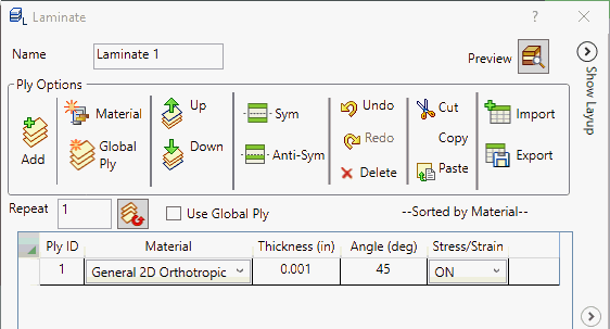
- With a
2 in the box beside the repeat button (1 is default), click the
Repeat button. The first row is copied two times. The following figure illustrates the result.
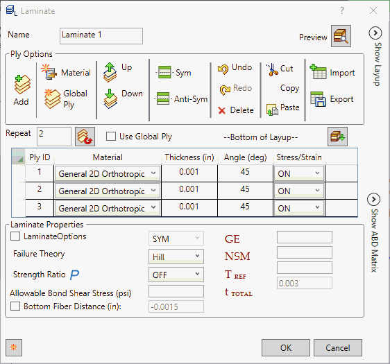
- Change the angles to 45, 0, and -45 from top to bottom.
- Now select all the Plies. Then click the Symmetric button.
- This will produce mirrored rows of the selected plies.
- The following figure illustrates the result.
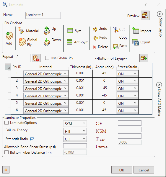
- Similarly, Anti-Symmetric would produce mirrored rows but with opposite signs for the ply angles.
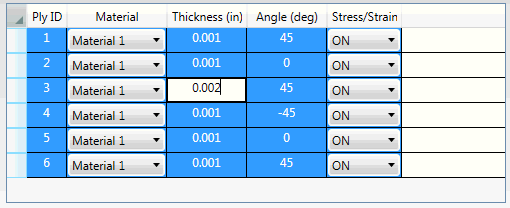
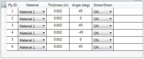
- You can select multiple
Plies and then right-click a field to change. Then select
Edit.
- Change the respective property of any ply, all the corresponding properties are changed at once.
Laminate Dialog Example:
- The lay up configuration in this example has three plies:

- In order to define the configuration of a 3-ply composite plane property, the Laminate Dialog entries would look as shown below. Note that the property is defined from the bottom up.
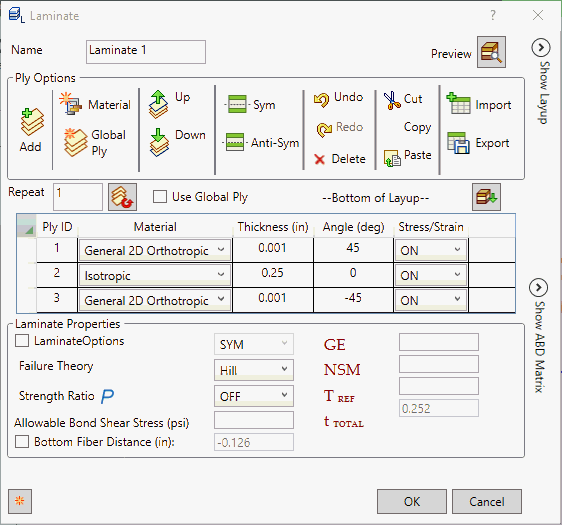
- Notice that the Bottom Fiber Distance is updated automatically (-1/2 total thickness). It is the distance from the reference plane to the bottom surface. Ply 1 is the bottom ply and the last ply defined is the top ply (ply 3 in this case).
- Click on
Preview button
 to view the
Show Layup and
Show ABD Matrix.
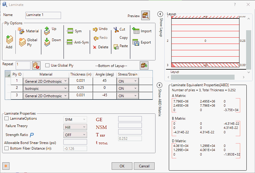
- Show Layup and Show ABD Matrix will individually expand when
 is clicked. In order to collapse, click the
 button.
- Show Layup: It represents the graphical representation of the plies defined by showing.
- Show ABD Matrix: Laminate equivalent properties are displayed in ABD matrix with number of plies and total thickness defined in the ply.
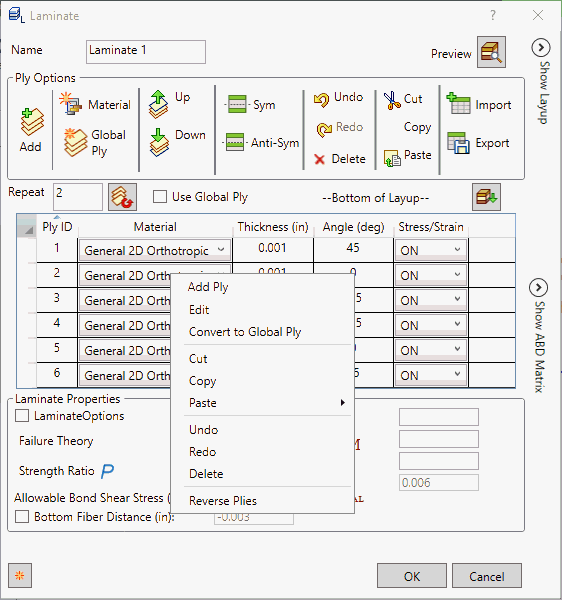
- Popup Menu: When we right-click on the rows, the popup menu is shown as below:
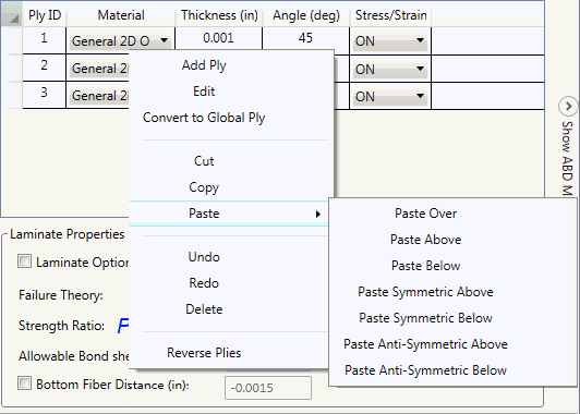
- Add Ply: Add new ply.
- Edit: Edit the property. Select any property say material, globalply, thickness. etc. Multiply selection with edit feature is used to change the value in all plies.
- Convert to Global Ply: It allows to convert normal ply to global ply definition.
- Cut: Cut the selected ply/plies.
- Copy: Copy the selected ply/plies.
- Paste: Paste the cut or copied ply/plies. It has different options paste over, paste above, paste below, paste symmetric above, paste symmetric below, paste anti-symmetric above and paste anti-symmetric below.
- Undo: Undo the operation performed.
- Redo: Redo the operation performed.
- Delete: Delete the selected ply/plies.
- Reverse Plies: Reverse the selected ply/plies.