Weld Element Property
Description: Defines the properties of a connector element (CWELD entry).
Format:

Example:

| Field | Definition | Type | Default | ||||
|---|---|---|---|---|---|---|---|
| PID | Property identification number. | Integer > 0 | Required | ||||
| MID | Material identification number. See Remark 2. | Integer > 0 | Required | ||||
| CTYPE | Weld connection type, one of the following character variables: SPOT or GENERAL. See Remark 3.
|
Character | GENERAL | ||||
| D | Diameter of the connector. See Remark 2. | Real > 0.0 | Required |
Remarks:
- PWELD entries must all have unique property identification numbers.
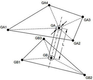
- Material MID, diameter D and the length are used to calculate the stiffness of the connector in all 6 component directions. MID can only refer to the MAT1 Bulk Data entry. The length is the distance of GA to GB as shown in Figure 1.
- For CTYPE = SPOT and FTYPE = ELEMID on the CWELD entry, the effective length for the stiffness of the weld element is set to
 regardless of the distance GA to GB.
tA and
tB are the shell thicknesses of SHIDA and SHIDB on the CWELD entry. For all other cases, the effective length of the weld element is equal to the true length, the distance of GA to GB, provided the ratio of length to diameter is in the range 0.2 ≤ L/D ≤ 5.0. If L is below this range, the effective length is set to
 , and if L is above this range, the effective length is set to
 .
.

Figure 1. Length and Diameter of the Weld Connector