Automated Impact Analysis
Description: Automated Impact Analysis (AIA). Automatically sets up a nonlinear transient impact analysis including contact definition, initial conditions, damping, time increment, and duration.
Format:
IMPACTGENERATE, gid, cid, v0, a, t1, t2, t3, tdelta, ttotal, nta, nto, desid
Example:
IMPACTGENERATE, 134, , 124.5, 386.4, 0.004, 1.05, 0.654
| Option | Definition | Type | Default |
|---|---|---|---|
| gid | Grid point identification number on projectile. See Remark 1. | Integer > 0 | Required |
| cid | Projectile translation vector, ti, coordinate system identification number. See Remark 2. | Integer ≥ 0 or -1 | 0 |
| v0 | Initial projectile velocity magnitude in the direction of the projectile translation vector. See Remark 3. | Real ≥ 0.0 | 0.0 |
| a | Projectile and part acceleration magnitude in the direction of the projectile translation vector. See Remark 4. | Real ≥ 0.0 | 0.0 |
| t1, t2, t3 | Projectile translation vector. | Real ≥ 0.0 | 0.0, 0.0, 0.0 |
| tdelta | Time increment. See Remark 5. | Real ≥ 0.0 | Model dependent |
| ttotal | Total duration. See Remark 6. | Real ≥ 0.0 | Model dependent |
| nta | Number of analysis time steps. See Remark 6. | Integer > 0 or blank | See Remark 6 |
| nto | Number of output time steps. See Remark 7. | Integer > 0 or blank | See Remark 7 |
| desid | Damped element set identification number. Set identification of previously appearing SET command. Only elements whose identification numbers appear on this SET command will be used. See Remarks 8 and 9. | Integer > 0 or blank | Projectile element set |
Remarks:
- gid is a point on the projectile through the projectile translation vector defined by ti. The grid point should be selected at the approximate impact point and defines the base of the projectile axis.
- A cid value equal to -1 specifies that the ti are in the basic coordinate system and the vector magnitude is the exact translation distance required to place the projectile on the surface of the body. A cid value greater than or equal to zero ignores the projectile vector magnitude and estimates the distance to impact by translating the projectile to the part so that it contacts near the vector base.
- The initial projectile velocity magnitude, v0, is required if the acceleration magnitude, a, is not specified.
- The acceleration magnitude, a, is required if the initial projectile velocity, v0, is not specified.
- The transient time increment may be omitted and a value based on the estimate of the contact frequency at impact will be used. The contact frequency is determined using
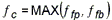
where
 is the natural frequency of the projectile fixed at the point of contact and
 is the natural frequency of the part fixed at the user defined boundary conditions. The time increment is then determined using

- Duration is the total time duration of the analysis. If both duration (ttotal) and the number of analysis time steps (nta) are omitted, a duration value will be calculated using
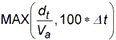
where
 is the projectile translation distance to impact,
 is the average velocity before impact equal to
 , and
, and
 is
tdelta if specified or the calculated time increment. When
nta is specified, a duration value will be calculated using
is
tdelta if specified or the calculated time increment. When
nta is specified, a duration value will be calculated using

-
If the MAXIMPACTSTEP model parameter is set to a value other than zero and nta is omitted, the transient time increment and duration will be adjusted to limit the number of output steps to MAXIMPACTSTEP (see Section 5, Parameters, for more information on MAXIMPACTSTEP). When nta and nto are both specified, the number of output steps is set to nto if nto is less than nta or nta if it is greater.
- The damped element set,
desid, is generally not required but may be needed for more complicated models where the object of interest is the projectile. It is used for the following:
- To define all elements and grid points contained in the projectile set when there is a discontinuity in a complex projectile such as a surface weld element between two discontinuous parts. By default the projectile set is automatically identified using the projectile grid point, gid. The body set is defined as all elements not in the projectile set. If there is a discontinuity in a complex projectile, it will be necessary to explicitly define the projectile using the damped element set, desid.
- To specify the object that the damping frequency of interest should be based on. This is typically the object of interest. When the damped element set is specified, the damping frequency is calculated using a normal modes analysis where the body is fixed and the frequency of the mode with the largest scaled displacement at the impact point in the direction of the projectile translation vector is used.
- When the damped element set, desid, is not specified, the damping frequency of interest is based on element structural damping. If element structural damping is specified on any element in the projectile set, the damping frequency will be based on a normal modes analysis of the projectile. Otherwise, the body is used as the basis where the projectile is fixed and a normal modes analysis is performed on the body.