Geometric Surface Element Definition (Property Form)
Description: Defines a boundary condition surface element with reference to a PHBDY entry.
Format:

Example:

| Field | Definition | Type | Default |
|---|---|---|---|
| EID | Element identification number. | Integer > 0 | Required |
| PID | Property identification number of a PHBDY entry. | Integer > 0 | Required |
| TYPE | Surface type, see Remark 3. | Character | Required |
| IVIEW | A VIEW identification number. | Integer > 0 | |
| Gi | Grid point identification numbers of connection points of the surface. | Integer > 0 | |
| G0 | Grid point identification number to optionally supply X1, X2, and X3. Direction of orientation vector is G1 to G0. | Integer > 0 or blank | |
| RADMID | RADM identification number. | Integer > 0 | |
| CID | Coordinate system for defining orientation vector. | Integer > 0 | 0 |
| Xi | Components of the orientation vector in the coordinate system defined in field 5. The origin of the orientation vector is a grid point G1. | Real or blank |
Remarks:
- Element identification numbers must be unique with respect to all other element identification numbers.
- For types POINT and LINE geometric orientation is required. The required information is sought in the following order:
- If G0 > 0 is found on the CHBDYP entry, it is used.
- Otherwise, if a non-blank CE is found on the CHBDYP continuation entry, this CE and the corresponding vectors E1, E2, and E3 are used.
- If none of the above apply, a warning message is issued.
- All conduction elements to which any boundary condition is to be applied must be individually identified with the application of one of either surface element entries: CHBDYG or CHBDYP.
- TYPE specifies the kind of element surface. Supported types are POINTS and LINE.
- TYPE = POINT
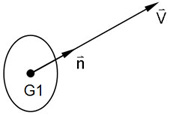
The POINT type has one primary grid point, requires a property entry, and the normal vector Vi must be specified.

Figure 1. Normal Vector for CHBDYP Element with Type Equal to POINT
The unit normal is given by:

- TYPE = LINE
The LINE type has two primary grid points, requires a property entry, and the vector is required.

Figure 2. Normal Vector for CHBDYP Element with Type Equal to LINE
The unit normal lies in the plane
 and
and
 , is perpendicular to
 , and is given by:

- TYPE = POINT
- The geometric orientation can be defined by either GO or the vector E1, E2, E3.
- If GO > zero:
For a POINT-type surface, the normal to the front face is the vector from G1 to GO. For the LINE-type surface, the plane passes through G1, G2, GO and the right-hand rule is used on this sequence to get the normal to the front face.
- If GO is zero:
For a POINT-type surface, the normal to the front face is the orientation vector. For the LINE-type surface, the plane passes through G1, G2, and the orientation vector; the front face is based on the right-hand rule for the vectors G2 - G1 and the orientation vector.
- If GO > zero: