Collision avoidance tilts the tool axis, in a user defined way, to avoid collisions between the shank/holder of the tool assembly and the model.
This page contains the following:
Tilt method — Choose how the tool moves to avoid a collision.
- Lean — If a collision is detected, the tool tilts from the original axis (specified on the Definition tab of the Tool Axis dialog) in the Lean direction until the collision is avoided. For more information, see Lead/Lean Angles or Fixed Angle.
- Lead — If a collision is detected, the tool tilts from the original axis in the Lead direction until the collision is avoided.
- Lead then Lean — If a collision is detected, the tool tilts from the original axis in the Lead direction until the collision is avoided. If the collision cannot be avoided by tilting the tool in the Lead direction, the tool tilts in the Lean direction until the collision is avoided.
- Lean then Lead — If a collision is detected, the tool tilts from the original axis in the Lean direction until the collision is avoided. If the collision cannot be avoided by tilting the tool in the Lean direction, the tool tilts in the Lead direction until the collision is avoided.
- Specified direction — If a collision is detected, the tool tilts such that the tool tip tries to point towards or away from geometry specified in the Specified direction frame.
- Automatic — If a collision is detected, the tool tilts away from the model until the collision is avoided. This option is suitable for models and toolpaths of all shapes and sizes.
Note: This option is only available if your tool axis is set to Vertical.
Holder clearance — Enter a specified “safe” area around the tool holder which is taken into account when checking for collisions.
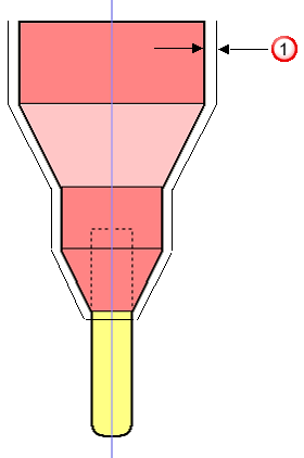
 Holder clearance
Shank clearance — Enter a specified “safe” area around the tool shank which is taken into account when checking for collisions.
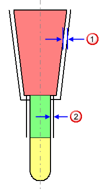
 Holder clearance
 Shank clearance
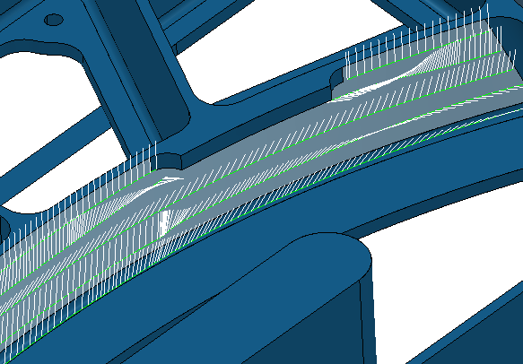
Smoothing distance — Enter the distance over which to smooth the tool axis movement. When using Stepped on Surface, or with sudden changes in direction in the original toolpath (such as a right-angled corner), you get rapid changes of orientation of the tool axis which leaves dwell marks. To prevent this, the Smoothing distance blends the change in orientation and gives a much improved surface finish.
It is easier to see the effect of changing the Smoothing distance if you draw the tool axis, click Toolpath tab > Draw panel > Display > Tool axes.
A Smoothing distance of 2
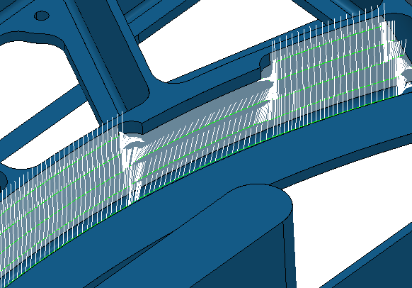
A Smoothing distance of 20

A Smoothing distance of 60
Tilt direction — Select how to specify the geometry used to orient the tool axis. This is available only if you select a Tilt method of Specified direction.
- Towards Line — If a collision is detected, the tool tip tilts from the original towards the line, until the collision is avoided, to become a Toward Line Tool Axis.
- From Line — If a collision is detected, the tool tip tilts from the original away from the line, until the collision is avoided, to become a From Line Tool Axis.
- Towards Curve — If a collision is detected, the tool tip tilts from the original towards the curve, until the collision is avoided, to become a Toward Curve Tool Axis. The curve must be a pattern with a single segment (selectable in the Pattern field).
- From Curve — If a collision is detected, the tool tip tilts from the original away from the curve, until the collision is avoided, to become a From Line Curve Axis. The curve must be a pattern with a single segment (selectable in the Pattern field).
- Surface Normal — If a collision is detected, the tool tip tilts from the original towards the Surface Normal direction until the collision is avoided.
- Fixed Direction — If a collision is detected, the tool tip tilts from the original towards the Fixed Direction until the collision is avoided.
- Blisk — If a collision is detected, the tool tip tilts from the original away from the specified surfaces. Select an option from the Path position list to specify the toolpath position:
Tilt pattern — Select the curve used when you select a Tilt method of Specify direction and a Tilt direction of Towards curve or From curve. The curve must be a pattern with a single segment.
 Create pattern — Click to create a new empty pattern.
 Selected pattern — Select a pattern from the list. If no pattern is displayed, or
 is selected, then no pattern is selected. The list contains a list of all available patterns.
Curve Editor — Click to display the Curve Editor tab, which enables you to create and edit patterns. The assumption is that you first extract curves from the model, and then modify the curve to create the exact pattern you need.
 Select picked pattern — Click to select a pattern by picking in the graphics window.
Clicking
 displays the
Pick Entity tab. Select a pattern in the graphics window to close the
Pick Entity tab and display the pattern in the
Selected Pattern field.
 Collect curves — Click to copy the selected curves into the pattern.This provides a fast, powerful means of extracting curve geometry from a surface model and copying it into the active pattern/boundary. For more information, see the
collecting curves example.
Point — Enter the coordinates of the fixed point.
 — Click to display the
Position
dialog. Use the dialog to manually enter coordinates and locate items in the graphics window.
Direction — Specify the direction of the line from the fixed point.
 — Click to display the
Direction
dialog, which enables you to edit the direction of an item.
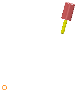
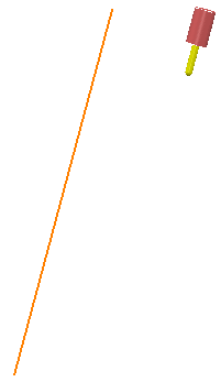
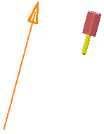
Draw tilt direction — Select to display the tool axis direction.
If you specify Towards Point or From Point, then PowerMill displays the specified point:
If you specify Towards Line or From Line, then PowerMill displays the specified line:
If you specify a Fixed Direction, then PowerMill displays the specified line with an arrow on it to indicate the direction:
If you specify a Lead, Lean, or Surface Normal, the option has no effect.
For more information see Basic collision avoidance example and Collision avoidance example.