Use the Turn groove roughing page to machine a groove feature in a turned part.
Style — Select an option to specify whether the groove depth or width is machined first.
- Depth first — Machine the full depth of the groove before stepping over.
- Width first — Machine the full width of the groove before stepping down.
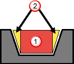
Plunge centre first — Select this option to start with a plunge into the centre of the groove.
For angled groove features, if
Plunge centre first is selected, the straight portion of the groove are roughed first and then the angled portions are roughed separately. For example, the red region
 is roughed first and then the yellow regions
 are roughed subsequently.
Below centreline — Select this option to make the tool work on the negative X side of the turning centreline.
Tolerance — Enter a value to determine how accurately the toolpath follows the contours of the model.
Cut direction — Select an option to specify the cutting direction of the tool:
- Positive — The tool cuts in the positive direction of the cutting axis, which depends on the selected
Cycle.
- Turn — The tool cuts in the +Z direction.
- Face — The tool cuts in the +X direction.
- Backface — The tool cuts in the +X direction.
- Negative — The tool cuts in the negative direction of the cutting axis, which depends on the selected
Cycle.
- Turn — The tool cuts in the -Z direction.
- Face — The tool cuts in the -X direction.
- Backface — The tool cuts in the -X direction.
Thickness — Enter the amount of material to be left on the part. Click the
Thickness
 button to separate the
Thickness
box in to
Radial thickness
button to separate the
Thickness
box in to
Radial thickness
 Axial thickness
 . Use these to specify separate
Radial and
Axial thickness as independent values. Separate
Radial and
Axial thickness values are useful for orthogonal parts. You can use independent thickness on sloping walled parts, although it is more difficult to predict the results.
. Use these to specify separate
Radial and
Axial thickness as independent values. Separate
Radial and
Axial thickness values are useful for orthogonal parts. You can use independent thickness on sloping walled parts, although it is more difficult to predict the results.
Radial thickness — Enter the radial offset to the tool. When 2.5-axis or 3-axis machining, a positive value leaves material on vertical walls.
Axial thickness — Enter the offset to the tool, in the tool axis direction only. When 2.5-axis or 3-axis machining, a positive value leaves material on horizontal faces.

Depth of cut — Enter a step increment for each pass that the roughing routine performs on the part.
Step over — Specify the distance between each cutting step as a percentage of the tool width.
Peck retract distance — Specify the distance the tool retracts between plunges.
Side liftoff distance — Enter the distance to move the tool after a plunge cut, in the direction opposite to the cutting direction. This value is ignored for the retract move at the end of the first plunge.
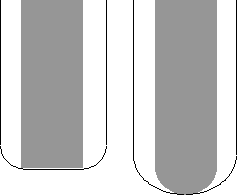
This part has a Groove feature, shown in pink:

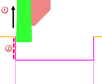
The default behavior is for the tool to lift off the part at 90 , shown in the following image by
, after each plunge cut. This results in tool contact with the uncut material, at
, when the tool is retracting at a rapid feed rate along the X axis:
, shown in the following image by
, after each plunge cut. This results in tool contact with the uncut material, at
, when the tool is retracting at a rapid feed rate along the X axis:
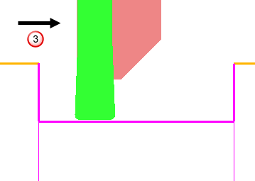
You can avoid this by using the
Side liftoff dist. attribute, to move the tool back along the Z axis
 , before lifting off.
Dwell — Enter the number of seconds you want to dwell after plunging.