Use the Create Holes dialog to create holes.
Click Hole Feature Set tab > Holes panel > Create to display the Create Holes dialog.
This dialog contains the following:
Name root — Enter a name for the hole. Each hole has the root name followed by a number. If there is no root name the hole just has a number.
Create from — Select how to recognise holes:
- Points — Select to create holes from points in the pattern. These points define the centre of the hole.
- Circles — Select to create holes from circles in the model.
- Model — Select to create holes from holes in the model.
- Pairs — Select to create holes from pairs of circles in the model.
- Curves — Select to create holes from any curve in the model that can flatten into a circle in the given workplane.
- Lines — Select to create holes from lines in the pattern. These lines define the top, bottom, and axis of a hole.
- Plunges — Select to create holes from the plunge moves of the active toolpath.
- Normals — Select to create holes from contact-normal moves of the active toolpath.
If you select a Create from of Model, the dialog options are different. For more information see Create Holes > From Model dialog.
 — Click to display the Curve Editor.
 — Click to display the Hole Creationpage of the Options dialog.
Define top by — These options determine the height of the top of the hole:
- Absolute — Select to define the top as an absolute Z height.
- Height from Bottom — Select to define the top as a distance from the bottom of the hole.
- Maximum Curve Z — Select to define the top as the maximum Z height of the selected curve, location
 .
. - Minimum Curve Z — Select to define the top as the minimum Z height of the selected curve, location
 .
. Maximum Z Minimum Z
 - Curve centre — Select to define the top as halfway between the top and bottom of the curve (midway between and ).
- Top of Block — Select to define the top as the height of the top of the block.
- Line Start — Select to define the top as the start of the line.
- This option is available only if you select a Create from of Lines.
 — Enter the height of the top of the hole feature.
This is available only if you have a Create from of Points, Circles, Curves, or Lines.
Define bottom by — These options determine the height of the bottom of the hole:
- Absolute — Select to define the bottom as an absolute Z height.
- Depth from Top — Select to define the bottom as a distance from the top of the hole.
- Maximum Curve Z — Select to define the bottom as the maximum Z height of the selected curve, location .
- Minimum Curve Z — Select to define the bottom as the minimum Z height of the selected curve, location . Maximum Z Minimum Z
- Curve centre — Select to define the bottom as half way between the top and bottom of the curve. Midway between and .
- Bottom of Block — Select to define the bottom as the height of the bottom of the block.
- Line End — Select to define the bottom as the end of the line.
This option is available only if you select a Create from of Lines.
- — Enter the height of the bottom of the hole.
This is available only if you have a Create from of Points, Circles, Curves, Lines, or Normal.
Upper diameter — Enter the upper diameter of the hole.
The Upper diameter is the same as the Lower diameter unless the hole has a Draft angle.
This is available only if you have a Create from of Lines, or Normal.
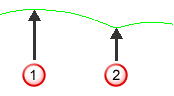
Draft angle — Enter the draft angle of the hole. A value of 0 gives a straight hole with no draft angle.
Draft angle of 0:

Draft angle of 10:
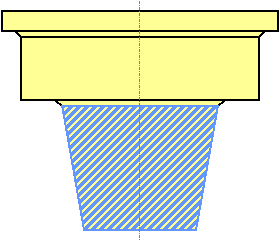
This is available only if you have a Use of Lines, or Normal.
Group holes by axis — When selected, sorts the holes into hole feature sets by workplane. In this case, your machine tool must have 3+2-axis drilling capability. When deselected, places all the holes in one hole feature set. In this case, your machine tool must have multi-axis drilling capability.
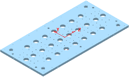
This example uses the RetainerPlate.dgk model. It has an active workplane, and the whole model is selected:
Deselecting Group holes by axis gives:
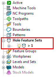
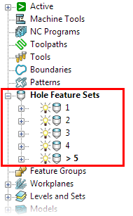
Selecting Group holes by axis gives:
Edit after creation — When selected, clicking Apply creates the holes and then displays the Edit Hole dialog.