Use the Parametric offset finishing page to machines between two curves. This strategy takes the rulings between two curves to generate the parametric offset toolpath.
Start curve — Select a pattern defining the start of the toolpath.

 The
End Curve.
The
End Curve.
 The
Start Curve.
The
Start Curve.
End Curve — Select a pattern defining the end of the toolpath.
 Select picked pattern — Click to select a pattern by picking in the graphics window, rather than by name in the
Select pattern list.
Select picked pattern — Click to select a pattern by picking in the graphics window, rather than by name in the
Select pattern list.
Clicking
displays the
Pick Entity tab. Select a pattern in the graphics window to close the
Pick Entity tab and display the pattern in the
Selected Pattern field.
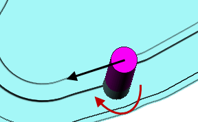
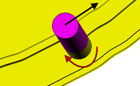
Offset direction — Select how the two curves are joined:
- Across — The toolpath goes from a point on the start curve to one on the second curve.

- Along — The toolpath is more like an offset toolpath radiating out from the start curve to the end curve.

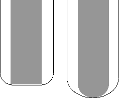
Limiting method — Select how the pattern limits the toolpath.
- Tip position — The tip of the tool follows the pattern.
- Contact position — The contact point of the tool follows the pattern.
Maximum offsets — Enter the maximum number of offsets.
Tolerance — Enter a value to determine how accurately the toolpath follows the contours of the model.
Cut direction — Select the milling technology.
Select a Cut Direction from the following:
- Climb — Select to create toolpaths using only climb milling, where possible. The tool is on the left of the machined edge when viewed in the direction of tool travel.
- Conventional — Select to create toolpaths using only conventional or upcut milling, where possible. The tool is on the right of the machined edge when viewed in the direction of tool travel.
- Any — Select to create toolpaths using both conventional and climb milling. This minimises the tool lifts and tool travel.
Thickness — Enter the amount of material to be left on the part. Click the
Thickness
 button to separate the
Thickness
box in to
Radial thickness
button to separate the
Thickness
box in to
Radial thickness
 Axial thickness
 . Use these to specify separate
Radial and
Axial thickness as independent values. Separate
Radial and
Axial thickness values are useful for orthogonal parts. You can use independent thickness on sloping walled parts, although it is more difficult to predict the results.
. Use these to specify separate
Radial and
Axial thickness as independent values. Separate
Radial and
Axial thickness values are useful for orthogonal parts. You can use independent thickness on sloping walled parts, although it is more difficult to predict the results.
Radial thickness — Enter the radial offset to the tool. When 2.5-axis or 3-axis machining, a positive value leaves material on vertical walls.
Axial thickness — Enter the offset to the tool, in the tool axis direction only. When 2.5-axis or 3-axis machining, a positive value leaves material on horizontal faces.

 Component thickness — Click to display the
Component thickness
dialog, which enables you to specify the thicknesses of the different surfaces.
Component thickness — Click to display the
Component thickness
dialog, which enables you to specify the thicknesses of the different surfaces.
Maximum stepover — Sets the upper limit of the distance between successive machining passes.
 Copy stepover from tool — Click to load the radial depth of cut from the active
tool's cutting data. The radial depth of cut is measured normal to the tool axis.
Copy stepover from tool — Click to load the radial depth of cut from the active
tool's cutting data. The radial depth of cut is measured normal to the tool axis.
 Edited — When displayed, shows value entered by you (or another user). Click
to change this value to the automatically calculated value.
Edited — When displayed, shows value entered by you (or another user). Click
to change this value to the automatically calculated value.
changes to
.
 Cusp height — Enter the maximum cusp height and use this value to determine the stepover.
PowerMill calculates the stepover value to give a cusp height of the machining tolerance using the current tool, when machining a plane inclined at 45
Cusp height — Enter the maximum cusp height and use this value to determine the stepover.
PowerMill calculates the stepover value to give a cusp height of the machining tolerance using the current tool, when machining a plane inclined at 45 . This is the worst case cusp height for any given tolerance.
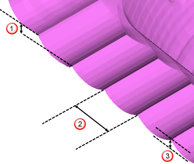
Stepdown
Stepover
 Cusp height
Preview — Click to display the pattern used to create the toolpath.
Draw — Select to display the preview pattern.