Use the Constant Z finishing page to create a toolpath by slicing the model at specific Z Heights.
Order by — Select whether machining takes place by Region or by Level.
- Region — When selected, one region (such as a pocket or boss) is completely machined before going on to the next. So, pockets are machined in preference to levels.

- Level —When selected, one level is completely machined before going down to the next. So, levels are machined in preference to pockets.

Spiral — Select this option to create a spiral path between two consecutive closed contours. This minimises the number of lifts of the tool and maximises cutting time while maintaining more constant load conditions and deflections on the tool.
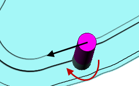
Spiral option — Deselected:

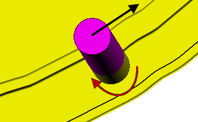
Spiral option —Selected:

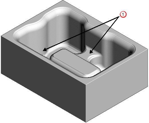
Undercut — Select this option to produce a toolpath where the cutter can touch the part, so you can machine areas with undercuts.
If you start with this model:

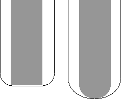
Undercut — Selected:

Undercut — Deselected:
 — Areas not fully machined.
- If a vertical tool axis is used, undercuts work with ball nosed, tapered spherical and tipped disc tools.
- If the tool axis is not vertical then undercuts work with ball nosed, tapered spherical and spherical tipped disc tools.
Not all tipped disc tools work with a non-vertical axis, only those with a (hemi)spherical end, (where diameter=2*tip radius).
Machine down to flats — Select this option to add a constant Z slice on flat surfaces at the bottom of steep features.
Machine down to flats — Selected:

— Flat surface
Machine down to flats — Deselected:

Flat tolerance — Enter the Z range that determines whether a surface is flat.
Tolerance — Enter a value to determine how accurately the toolpath follows the contours of the model.
Cut direction — Select the milling technology.
Select a Cut Direction from the following:
- Climb — Select to create toolpaths using only climb milling, where possible. The tool is on the left of the machined edge when viewed in the direction of tool travel.
- Conventional — Select to create toolpaths using only conventional or upcut milling, where possible. The tool is on the right of the machined edge when viewed in the direction of tool travel.
- Any
— Select to create toolpaths using both conventional and climb milling. This minimises the tool lifts and tool travel.
Note: Any allows zigzag cutting on open toolpath segments. Closed segments default to Climb cutting. To change the cut direction for closed segments, click Toolpath Edit tab > Edit panel > Reorder.
Thickness — Enter the amount of material to be left on the part. Click the
Thickness
 button to separate the
Thickness
box in to
Radial thickness
button to separate the
Thickness
box in to
Radial thickness
 Axial thickness
 . Use these to specify separate
Radial and
Axial thickness as independent values. Separate
Radial and
Axial thickness values are useful for orthogonal parts. You can use independent thickness on sloping walled parts, although it is more difficult to predict the results.
. Use these to specify separate
Radial and
Axial thickness as independent values. Separate
Radial and
Axial thickness values are useful for orthogonal parts. You can use independent thickness on sloping walled parts, although it is more difficult to predict the results.
Radial thickness — Enter the radial offset to the tool. When 2.5-axis or 3-axis machining, a positive value leaves material on vertical walls.
Axial thickness — Enter the offset to the tool, in the tool axis direction only. When 2.5-axis or 3-axis machining, a positive value leaves material on horizontal faces.

 Component thickness — Click to display the
Component thickness
dialog, which enables you to specify the thicknesses of the different surfaces.
Component thickness — Click to display the
Component thickness
dialog, which enables you to specify the thicknesses of the different surfaces.
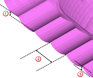
Stepdown
Minimum stepdown — Enter the constant stepdown value between successive machined levels.
 Copy stepdown from tool
— Click to load the axial depth of cut from the active
tool's cutting data. The axial depth of cut is measured along the tool axis.
Copy stepdown from tool
— Click to load the axial depth of cut from the active
tool's cutting data. The axial depth of cut is measured along the tool axis.
Calculate using cusp — Select this option to determine the stepdown by the Cusp height, with a maximum stepdown determined by the Maximum stepdown value. When deselected, the stepdown between successive Z heights has a constant value equal to the Minimum Stepdown value.
Maximum stepdown — Enter the maximum allowable stepdown when calculating the stepdown using the cusp height. This prevents excessive stepdown on vertical walls.
Cusp height — Use this setting to specify the stepdown so that the height of the material left between Z Heights does not exceed the Cusp Height. However, if the calculated value is smaller than the Minimum Stepdown, it is set to Minimum Stepdown.
Stepdown
 Stepover
 Cusp height