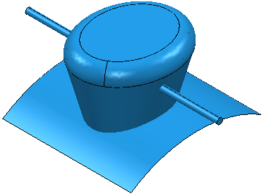
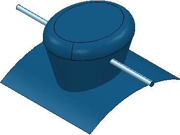
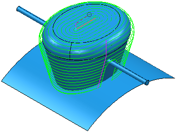
This examples shows you how to create parametric spiral finishing toolpath. This uses:
- The Boss.dgk and Pins.dgk model in the Examples folder.
- The CentralCurve.dgk pattern in the Examples > Patterns folder.
- A rectangular Block.
- A 10 mm ball nosed tool.

The toolpath must machine the boss and avoid the pins.
In Parametric Spiral Finishing toolpaths, surfaces with a Machining Mode of Collision behave differently to other strategies.
In parametric spiral toolpaths:
- A spiral pattern is created by ignoring the surfaces set to Collision.
- The pattern is lifted above the surfaces set to Collision along the projection direction of the tool.
This enables fast creation of the toolpath.
- To avoid machining the pins, select the pin.

- Click Home tab > Toolpath Setup panel > Thickness to display the
Thickness Preferences dialog.
- Select the Surface Defaults tab.
- Select the top set in the list of sets in the bottom of the dialog.
- Click
 Acquire Components
to place the pins in this set. The number of selected
Components changes to
1.
- Select a Machining Mode of Collision.
- Click Accept.
- Click Home tab > Create Toolpaths panel > Toolpaths to display the Strategy Selector dialog.
- From the
Finishing category select
Parametric Spiral Finishing.
- Select a Central curve of the pattern you created from CentralCurve.dgk.
- Select an Outer limit of Surfaces.
- Enter a Left angle of 15.
- Enter a Right angle of 15.
- Enter a Maximum stepover of 5.
- Click Calculate.
