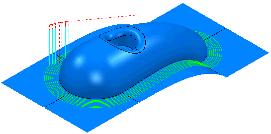
This example looks at a contact point toolpath. Typically this is used where you want to define the exact position of a toolpath. This uses the Cowling.dgk model in the Examples folder.
- Create a Block and a Tool.
- Click Pattern tab > Create panel > Pattern.
- Click Pattern tab > File panel > Import.
The Open Pattern dialog is displayed.
- In the Examples\Patterns directory open Cowling_ContactPoint.dgk.
- To embed the pattern, from the individual Pattern context menu select the Edit > Embed. This displays the Embed Pattern dialog.
- On the Embed Pattern dialog:
- select a Method of Drop (as the pattern is above the model)
- click Apply.
This creates an Embedded Pattern which is marked by
 in the Explorer. The original pattern is also kept.
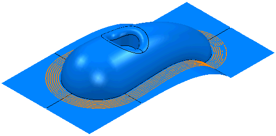
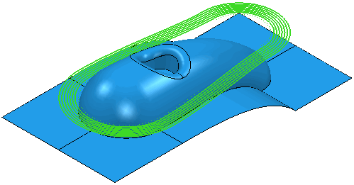
- Click Home tab > Create Toolpaths panel > Toolpaths to display the Strategy Selector dialog.
- From the Finishing category, select Embedded Pattern Finishing.
- On the Embedded pattern finishing page:
- In the Drive Curve frame, select an Embedded Pattern of Cowling_Contact Point_1 (created above).
- In the Lower Limit frame, select an Axial Offset of 0.
- In the Gouge Avoidance frame select Gouge Check. Since you are specifying the exact location of the toolpath you want to ensure that the toolpath does not gouge the surface.
- On the Gouge avoidance page:
- Deselect Upper Limit since you are creating a single pass.
- Select a Strategy of Trace.
- On the Multiple cuts page:
- Select a Mode of Off.
- Click Calculate.