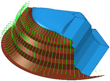
Use the Surface projection finishing page to create a toolpath which is a type of drive surface machining. You must select a reference surface for this strategy to work. The pattern is created on this reference surface. The reference surface does not have to be the surface you want to machine, it can be a construction surface.
Surface units — Select the units used to specify the stepover and limits.
- Distance — The physical distance determines the stepover and limits. The first and last pass are on the edge of the surface. The intermediate passes are at a distance that is less than or equal to the specified Stepover.
- Parametric — The parameterisation of the surface determines the stepover and limits .
- Normalised — The surface normalised value ( in the range [0,1]) determines the stepover and limits. For example if the minimum U is 1 and the maximum U is 5 then:
|
Parametric value |
Normalised value |
|---|---|
|
1 |
0 |
|
2 |
0.25 |
|
3 |
0.5 |
|
4 |
0.75 |
|
5 |
1 |
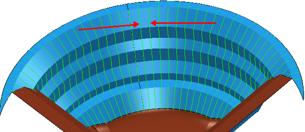
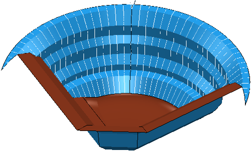
Projection direction — Select the direction to determine which regions are machined.
Select Inwards to project the surface pattern in the opposite direction to the surface normals by taking the pattern points far from the surface in the direction of surface normals.

Select Outwards to project the surface pattern in the direction of the surface normals by taking the pattern points far from the surface in the opposite direction of surface normals.
Tolerance — Enter a value to determine how accurately the toolpath follows the contours of the model.
Thickness — Enter the amount of material to be left on the part. Click the
Thickness
 button to separate the
Thickness
box in to
Radial thickness
button to separate the
Thickness
box in to
Radial thickness
 Axial thickness
 . Use these to specify separate
Radial and
Axial thickness as independent values. Separate
Radial and
Axial thickness values are useful for orthogonal parts. You can use independent thickness on sloping walled parts, although it is more difficult to predict the results.
. Use these to specify separate
Radial and
Axial thickness as independent values. Separate
Radial and
Axial thickness values are useful for orthogonal parts. You can use independent thickness on sloping walled parts, although it is more difficult to predict the results.
Radial thickness — Enter the radial offset to the tool. When 2.5-axis or 3-axis machining, a positive value leaves material on vertical walls.
Axial thickness — Enter the offset to the tool, in the tool axis direction only. When 2.5-axis or 3-axis machining, a positive value leaves material on horizontal faces.

 Component thickness — Click to display the
Component thickness
dialog, which enables you to specify the thicknesses of the different surfaces.
Component thickness — Click to display the
Component thickness
dialog, which enables you to specify the thicknesses of the different surfaces.
Stepover — Enter the distance between successive machining passes.
Preview — Click to produce a quick preview toolpath over the projection shape.
Draw — Select to display the preview pattern.