If PowerMill cannot work out the drive or limit curves then you can select them. This example uses the 5axisModel.dgk model in the Examples folder and assumes you have created an embedded pattern.

- From the Finishing category on the Strategy Selector dialog, select Flowline finishing.
- Select the embedded pattern. If the Status is Valid go to step 9.
- If the
Status is anything other than
Valid, click on the
Curve definition button
 . This displays the
Flowline Curve Definition dialog.
. This displays the
Flowline Curve Definition dialog.
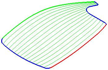
- Select the start drive curve.
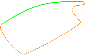
The start drive curve is green.
- Select the end drive curve.

The end drive curve is red.
- Select a limit curve.
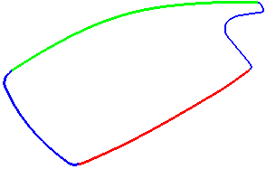
The limit curve is blue.
- Select the second limit curve (use the
Shift key whilst selecting it).

The second limit curve is blue and the cut direction and machining area are also defined.
- Click Finish. This closes the dialog and returns you to the Flowline Finishing dialog.
- On the
Flowline finishing page:
- Enter a Stepover of 10.
- Click
Calculate.