Use the items on the Tool tab > Draw panel to draw and view various aspects of the active tool.
Tool
Click Tool tab > Draw panel > Tool to draw the active tool in the graphics window.
Display
Use the following options on the Tool tab > Draw panel > Display menu to draw tool elements in the graphics window:
- Shank — Displays the tool shank.
- Holder — Displays the tool holder. When you draw the holder, the shank is also drawn.
- Tool Axis Definition — Displays the point or line used to define the tool axis in red.
- Select any
Tool Axis of
Toward Point or
From Point. This displays the location of the point.
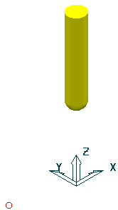
- Select any
Tool Axis of
Toward Line or
From Line. This displays the location of the line.

- Select any
Tool Axis of
Toward Curve or
From Curve. This displays the location of the curve.
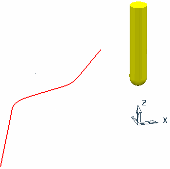
- Select any
Tool Axis of
Fixed Direction. This displays the following:
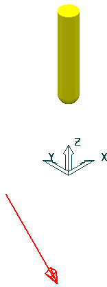
- Select any
Tool Axis of
Toward Point or
From Point. This displays the location of the point.
- Tool Axis Limits — Displays a graphic of the machinable portion.
For example:
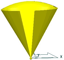
The portion of the sphere (or cone with a spherical top) is centred at the origin of the active workplane. If no active workplane exists, then it is placed at the origin of the global coordinate system. The origin is depicted by a small sphere. This graphic is displayed at an arbitrary size, and if you zoom in or out and then refresh the display, the size of this graphic changes. This is to ensure that it is visible whatever the zoom factor.
- Tool Axis Tilt Direction — Displays the tool axis direction.
- If you specify
Towards Point
or
From Point,
then
PowerMill displays the specified point:

- If you specify
Towards Line
or
From Line, then
PowerMill displays the specified line:
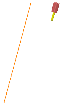
- If you specify a
Fixed Direction, then
PowerMill displays the specified line with an arrow on it to indicate the direction:
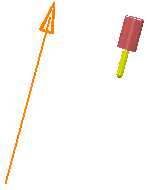
- If you specify a Lead, Lean, or Surface Normal, the option has no effect.
- If you specify
Towards Point
or
From Point,
then
PowerMill displays the specified point:
Shaded
Click Tool tab > Draw panel > shaded to toggle the appearance of tools drawn in the graphics window:
- Selected — Displays a shaded tool.

- Deselected — Displays a wireframe tool.
