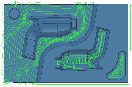
Use the Curve area clearance page to create a simple 2.5D raster, offset, or Vortex roughing toolpath.
Curve definition specifies the curves bounding the area you want to machine and adds the machining properties to those curves.
 Create pattern — Click to create a new empty pattern.
 Selected pattern — Select a pattern from the list. If no pattern is displayed, or
 is selected, then no pattern is selected. The list contains a list of all available patterns. When you have selected a pattern, the machining area is shaded.

If the shaded area is not what you want to machine, use the Curve machining properties
 button to alter the machining conditions.
 Curve Editor — Click to display the
Curve Editor tab, which enables you to create and edit patterns. The assumption is that you first extract curves from the model, and then modify the curve to create the exact pattern you need.
Curve Editor — Click to display the
Curve Editor tab, which enables you to create and edit patterns. The assumption is that you first extract curves from the model, and then modify the curve to create the exact pattern you need.
 Select picked pattern — Click to select a pattern by picking in the graphics window, rather than by name in the
Select pattern list.
Select picked pattern — Click to select a pattern by picking in the graphics window, rather than by name in the
Select pattern list.
Clicking
displays the
Pick Entity tab. Select a pattern in the graphics window to close the
Pick Entity tab and display the pattern in the
Selected Pattern field.
 Collect curves — Click to copy the selected curves into the pattern. This provides a fast, powerful means of extracting curve geometry from a surface model and copying it into the active pattern/boundary. For more information, see the
collecting curves example.
Collect curves — Click to copy the selected curves into the pattern. This provides a fast, powerful means of extracting curve geometry from a surface model and copying it into the active pattern/boundary. For more information, see the
collecting curves example.
- which regions of the curve are machined
- which side of the curve is machined
- the machining strategy.
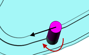
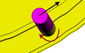
Position — Select an option to specify which part of the tool follows the curve.
 Centre
— The centre of the tool follows the curve.
Centre
— The centre of the tool follows the curve.
 Contact — The contact point of the tool follows the curve.
Lower limit — Enter or select the machining height. All curves are machined at a single Z height.
Either enter a value in the
Floor Z field, or select
 and then click on a curve at the relevant Z height in the graphics window.
The area clearance toolpath starts at the Z height of the pattern and works down the part, by the
Stepdown value, until the
Floor
 value is reached.

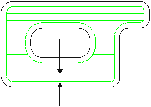
Style — Select the raster, offset, or Vortex style to remove the material enclosed within the contours on each roughing level.
- Raster — This comprises of parallel straight-line moves in the X - Y plane.

- Offset — This clears an area with contours generated by repeatedly offsetting the initial slice until no further offset is possible.

- Vortex — This produces an offset toolpath which never exceeds the maximum tool engagement angle for optimum machining. As the tool approaches the maximum engagement angle, the toolpath changes to a trochoidal path to avoid tool overload.
Model:
Feature group:
 Note: Vortex toolpaths are 3-axis toolpaths, so have a vertical tool axis.
Tolerance — Enter a value to determine how accurately the toolpath follows the contours of the model.
Cut direction — Select the milling technology.
Select a Cut Direction from the following:
- Climb — Select to create toolpaths using only climb milling, where possible. The tool is on the left of the machined edge when viewed in the direction of tool travel.
- Conventional — Select to create toolpaths using only conventional or upcut milling, where possible. The tool is on the right of the machined edge when viewed in the direction of tool travel.
- Any — Select to create toolpaths using both conventional and climb milling. This minimises the tool lifts and tool travel.
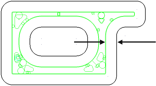
Curve thickness — Enter the offset of the curve. This is a curve, not a model thickness.
Stepover — Enter the distance between successive area clearance passes at a single Z height.

 Copy stepover from tool — Click to load the radial depth of cut from the active
tool's cutting data. The radial depth of cut is measured normal to the tool axis.
Copy stepover from tool — Click to load the radial depth of cut from the active
tool's cutting data. The radial depth of cut is measured normal to the tool axis.
 .
.
Rest machining — Select to enable the Rest page. Rest machining enables you to use a large tool for efficient volume removal and then a smaller tool to machine areas of the model that the large tool could not reach such as pockets and corners. The smaller tool machines only the areas that could not be reached by the original tool.