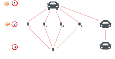
Assembly modelling allows you to quickly and easily generate complex assemblies of standard components. You can register solids as component definitions, and then create many instances of the component in an assembly. For example, a car can be an assembly consisting of four wheel components and one body component. Each wheel component is created from the same wheel component definition. The body component is created from the body component definition.
In addition to components, assemblies also contain a set of relations, specifying how the components fit together using attachments, as well as various tools to analyze the created assembly.
- Component definition — A mechanism for storing the geometry of a graphical object. The graphical object may be used to represent a complete engineering component, such as a car part.
Component definitions are automatically created when you create a component from a user-defined solid, a solid with Power Features, or when you add a component from a component library. When a component definition is created, it is stored invisibly. You can then use the definitions to create graphical components, and build the assembly.
- Component — Visible objects created from instances of component definitions, in particular positions and orientations in your model. A collection of components in an assembly is known as a group, but groups do not define the assembly hierarchy.
- Assembly — A collection of components, which fit together according to specified relations. For example, in a car assembly, you can create four wheel components and a body component. The assembly also stores information on how these fit together to create the car:

 Assembly.
 Component.
 Component definition.
It is also possible to create sub-assemblies; existing assemblies that form part of another assembly.
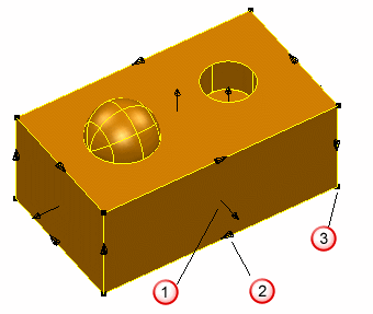
- Attachment — Components can be attached to other components in an assembly using attachments. Attachments are planar faces, axes, straight edges, or points on components, where another component can be attached. When you register a component, all the possible attachments are found automatically.
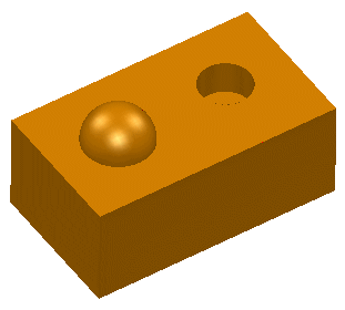
In the example below, the attachments are generated as follows:
 Plane
Plane
 Line
Line
 Point
Point


- Relation — a relationship between attachments on different components. For example, a planar attachment can be co-planar with another planar attachment, or it can be parallel by a given distance.
- Relationships that define the position of the component itself (because it is attached to another component) are called Secondary relations.
- Relationships that define the position of other components (because they are attached to a primary component) are called Primary relations.
The primary relation of one component is always matched by the secondary relation on the second (related) component. Relations are displayed in the Assembly Tree, under the Primary or Secondary Relations branch of the components.
- Sub-item — Each item in an assembly can have associated sub-items. For a component, the sub-item can be the solid the component is created from, or the workplane of the component. For a sub-assembly, the sub-items are the components inside the sub-assembly. For a group, the components are the sub-items.