Specify how you want isometric objects to be annotated in the drawing.
- Click Home tab
 Project panelProject ManagerProject Setup.
- In the Project Setup dialog box, expand Isometric DWG Settings. Click Annotations.
- On the Annotations pane, in the Iso Style list, select an iso style for which you want to set annotations.
- Under Settings tab, do the following:
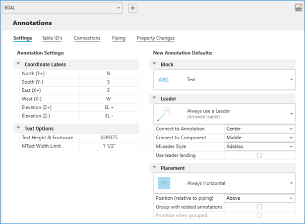
- Specify the coordinate labels of the annotations.
- Specify the text height of the annotations.
- Specify the width limit of the mtext annotations.
- Specify default settings of new annotations such as block, leader styles, annotation placement, and other related settings.
- Under Table ID's tab, do the following:
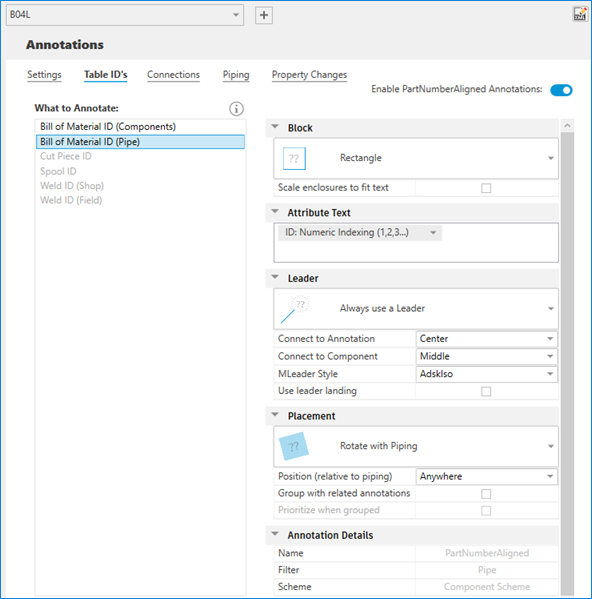
- Control the display of the selected annotation. You can specify individual annotations for BOM ID for pipe and non-pipe components, and shop and field welds. You can specify annotations for cut piece pipe and spool.
- In the What to Annotate list, select an annotation.
- Under Block, choose a text or a block to enclose the selected annotation. You can also choose whether to scale the enclosure shape.
- Under Attribute Text, select the numbering style either alphabetic or numeric, or specified from the model. You can also add text prefix or suffix to ID.
- Under Leader, choose a leader style or no leader line at all. You can specify the connection point for both annotation and component. You can also choose the multileader style and whether to use leader landing or not.
- Under Placement, choose the annotation to be always horizontal, rotate with piping, or to show in iso plane. You can also choose whether to place group with related annotations and prioritize current annotations when grouped.
- Under Annotation Details, view the name, filter, and scheme of the selected annotation defined in IsoConfig.xml.
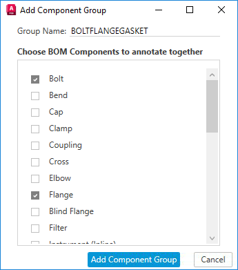
- In Bill of Material ID (Components) annotation, you can customize the component group and do the following:
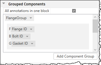
- Add, remove, enable, or disable a component group
- Add, remove, or reorder components in the component group
- Under Connections tab, do the following:
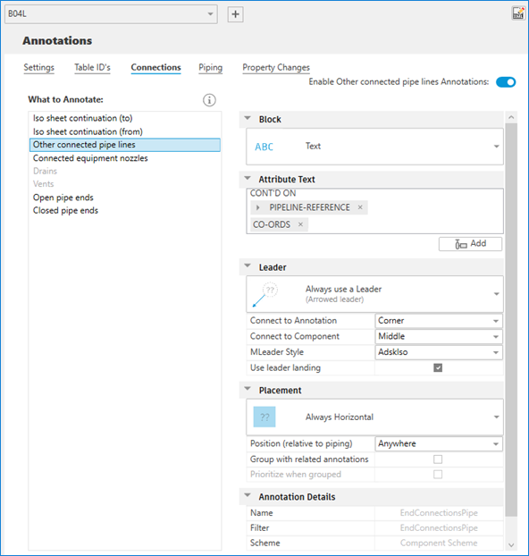
- Control the display of the selected annotation.
- In the What to Annotate list, select an annotation.
- Under Block, choose a text or a block to enclose the selected annotation. You can also choose whether to scale the enclosure shape.
- Under Attribute Text, do the following:
- Modify the connection text prefix or suffix as needed.
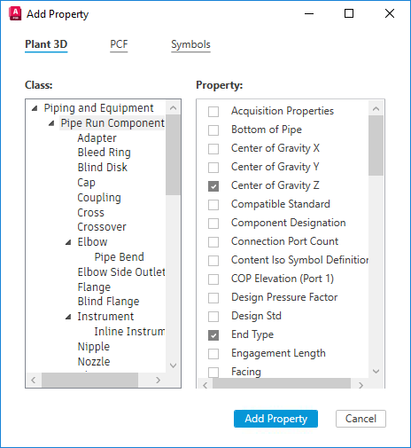
- Choose the properties from Plant 3D or PCF.
- Choose special symbols.
- Expand particular properties to add properties.
- Under Leader, choose a leader style or no leader line at all. You can specify the connection point for both annotation and component. You can also choose the multileader style and whether to use leader landing or not.
- Under Placement, choose the annotation to be always horizontal, rotate with piping, or to show in iso plane. You can also choose whether to place group with related annotations and prioritize current annotations when grouped.
- Under Annotation Details, view the name, filter, and scheme of the selected annotation defined in IsoConfig.xml.
- Under Piping tab, do the following:
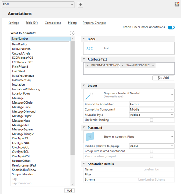
- Control the display of the selected annotation.
- In the What to Annotate list, select an annotation.
- Under Block, choose a text or a block to enclose the selected annotation. You can also choose whether to scale the enclosure shape.
- Under Attribute Text, do the following:
- Modify the connection text prefix or suffix as needed.
- Choose the properties from Plant 3D or PCF.
- Choose special symbols.
- Expand particular properties to add properties.
- Under Leader, choose a leader style or no leader line at all. You can specify the connection point for both annotation and component. You can also choose the multileader style and whether to use leader landing or not.
- Under Placement, choose the annotation to be always horizontal, rotate with piping, or to show in iso plane. You can also choose whether to place group with related annotations and prioritize current annotations when grouped.
- Under Annotation Details, view the name, filter, and scheme of the selected annotation defined in IsoConfig.xml.
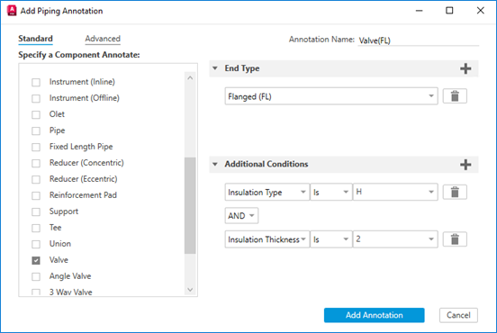
- At the bottom of the What to Annotate list, click Add to add a new piping annotation.
- Click OK.