Deflections of the beam need to be checked under two circumstances: construction loading with non-composite strength, and in full composite bending under service loads. If camber is selected, it also affects the results of deflection calculations.
Camber
If you selected to use camber, it is calculated before any deflections. Then it is used to determine the true deflections under service loads. By default, 80 percent of the self-weight deflection is cambered, with minimum, maximum, and step sizes as set by the user. Since deflections may be irregular and may not have their maximum at the center of the beam, the camber can be computed at any point along the beam by assuming that the beam is cambered in a circular arc. The radius r of the arc can be found from the amount of camber used 'c' and the length of the beam l:

and then the camber at any offset 'x' can be found by:

Construction deflections
During construction, the stiffness (and therefore the deflection) of the section comes only from the non-composite steel section. For each beam, the deflections under the self-weight of the slab, the weight of the steel section, and any other construction loads are calculated and compared to user-set limits. The stiffness E and moment of inertia I of the steel section are used for deflection calculations.
If the beam is to be cambered, this camber is calculated first. The deflection at a point is defined as the camber at that point subtracted from the deflection of the beam under the given loads. These are calculated under service (that is, unfactored) loads. The load types that are included in this calculation are:
- Construction dead loads (superimposed loads, other than the self-weight of the system)
- Construction live loads (also superimposed)
- Material self-weights.
Construction deflection limits can be set to either an absolute amount (default is 2 in) or a relative ratio (default is L/500).
Service deflections
Deflections of the beam under service loads are evaluated under two criteria:
- Total deflections under service dead and live loads (combined)
- Deflections under service live loads only (live).
Live load deflections
In the live load deflection case, the deflections under live loads only are calculated. Camber is not included in these calculations. This test is designed to represent the differential movement of the beam during occupancy, and is only based on the stiffness and moment of inertia of the composite section (see below for method of computing the stiffness of concrete sections). Live load deflection is limited in both a user defined absolute amount (default is 2 in) or a user defined relative amount (default is L/360).
Combined load deflections
In the combined case, the maximum deflection is defined as the total deflection under all service loads minus the camber in the beam. It represents how much the beam sags from centerline at any point along its length. However, since the self-weight deflections occur during non-composite action while the live load deflections occur during composite action, the stiffness and inertia of the beams is different for each case, and they must be calculated separately and then added. Therefore, the total deflection in the combined case is equal to the sum of self-weight deflections (using I and E for the steel) plus the deflections from all other service loads (using I and E for the composite section) minus the camber (which is based on a percentage of the self-weight deflections). Combined deflection is limited in both an absolute amount (default is 2 in) or a relative amount (default is L/240).
Moment of inertia of a composite section
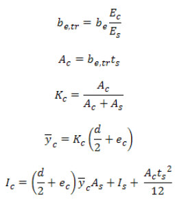
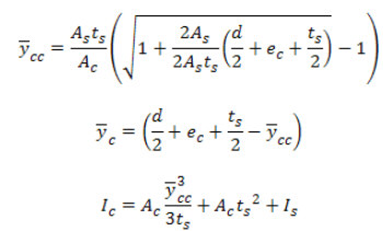
Calculations of service load deflections require the use of an effective moment of inertia based on the elastic properties of the composite section. Properties are computed based on the section geometry and (for partial composite action) the percent of full composite action developed by the studs. The long-term creep associated with the concrete is neglected for the purposes of these calculations.
The first step is to evaluate whether the Elastic Neutral Axis (E.N.A.) is in slab or the steel section. This can be found by the following tests. Depending on the condition, the transformed moment of inertia of the elastic composite section is computed using the approach given in Cheu (1996).
If

E.N.A. is in the steel:

If

E.N.A. is in the slab:

where:
E c / Es = n - modular stiffness ratio

y c - distance from steel centroid to elastic neutral axis
ec - distance from top steel flange to centroid of effective concrete flange
Is - moment of inertia of steel section
Ic - transformed moment of inertia of fully composite section
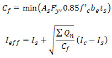
The effective moment of inertia for the partial composite section, I eff (which is used for all service load deflection calculations) is then computed using equation C-I3-3 from the commentary of ANSI/AISC 360-10, based on the ratio of the stud strength ( ) to the fully composite compression flange force Cf:
