Values of reduced forces should be obtained for 6 cross-sections described as follows.
Position of allowable cross-sections for reduced results

In order for cross-sections 1, 3, 4 and 6 to be correctly defined within panels (no defined coordinates), move the cross-sections by the Delta value with respect to the main panel nodes N1, N2, N3 and N3. The delta value equals the tolerance value applied in the generation of the calculation model.
The following point positioning is obtained.
Point M1 is the center of segment N1-N2.
Point M2 is the center of segment N2-N3.
Point M3 is the center of segment N3-N4.
Point M4 is the center of segment N4-N1.
Point C is the center of segment M1-M3 or is the center of segment M2-M3
Point M1' is the point of intersection between the line (M1,M3) and the panel edge.
Point M2' is the point of intersection between the line (M2,M4) and the panel edge.
Point M3' is the point of intersection between the line (M1,M3) and the panel edge.
Point M4' is the point of intersection between the line (M2,M4) and the panel edge.
Calculation of Reduced Forces
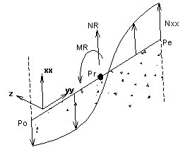
The coordinate system for results is identical to the coordinate system for results used in panel cuts.
The beginning of coordinate system is located in point Pr (Reference point) that is identical with M1, M2, M3, M4 or C, depending on the required cross-sections.
Points Po and Pe will be identical with Points N1 and N4 for cross-section 1.
Points Po and Pe will be identical with Points N2 and N3 for cross-section 3.
Points Po and Pe will be identical with Points N1 and N2 for cross-section 4.
Points Po and Pe will be identical with Points N3 and N4 for cross-section 6.
Points Po and Pe will be identical with Points M1' and M3' for cross-section 2.
Points Po and Pe will be identical with Points M2' and M4' for cross-section 5.
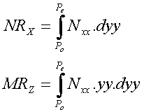
Calculation of NRx and MRz
Sign convention for normal forces and reduced
bending moments (NRx and MRz)


MRz moment has a positive value when it results in tension of fibers on the positive side of axis yy.
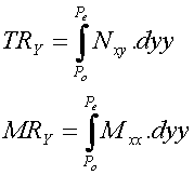
Calculation of other components of results

The sign convention applicable to MRy moment is identical to that applicable for Mxx moments. MRY moment has a positive value, when it results in tension of fibers on the positive side of the local axis z for panels.

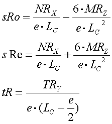
Calculation of reduced stresses sigma and tau
The components are necessary to check the reinforcement introduced in RC walls.

where:
sRo - The least value of vertical stresses in the wall (negative values - compression).
sRe - The greatest value of vertical stresses in the wall (positive values - tension).
e - Panel thickness.
Lc - Section length.
Reduction e/2 along the section length allows one to recognize reinforcement cover at the ends of bracing walls.
Calculation of section length Lc
The information is necessary to check the reinforcement introduced in RC walls.

where:
Xpo, Ypo and Zpo are absolute coordinates of point Po
Xpe, Ype and Zpe are absolute coordinates of point Pe.
Calculation of panel height Ht
The information is necessary to check the reinforcement introduced in RC walls.
For horizontal sections 1, 2 and 3, height Ht will be calculated on the basis of the following formula.

For vertical sections 4, 5 and 6, height Ht will be calculated on the basis of the following formula.
