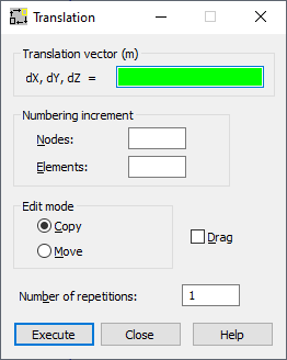
You can perform translation of selected structure nodes or elements, using either method:
- Click Edit menu > Edit > Translate.
- Click
 .
.

To define a translation, set the main parameters in the following fields of the Translation dialog:
- Nodes - Specifies the node numbering increment when defining new nodes.
- Elements - Specifies the element numbering increment when defining new elements.
- Move - When selected, the selected nodes or elements are moved in the structure (origin nodes or elements change their location in the structure).
- Copy - When this option is selected, new nodes or elements are created in a structure (origin nodes or elements remain the same).
- Drag - When selected, additional elements will be created between the existing nodes and the nodes created during editing. These elements are numbered automatically.
- Number of repetitions - Defines the number of repetitions for edit operations. The edit option can be repeated while changing the active selection for recently created elements or nodes..
Also, define the translation vector in the (dX, dY, dZ) field for the 3D view or in the (dX, dY) field for the 2D view.
After you defined the translation vector graphically, Robot translates selected elements or nodes, or if no objects have been selected, click Select in the context menu to select them. Robot remains in translation mode until the next command is selected or the <Esc> key is pressed.
If you manually defined the translation vector in the dialog, clicking Execute completes the action.
If you have selected only bars (without nodes), Robot translates these bars by a translation vector without changing the position of adjoining bars. If you have selected nodes of a bar, Robot snaps the adjoining bars to a new position of the translated node.
After selecting the Grid or Auto cursor mode, the coordinates for the translation vectors are displayed in the (dX, dY, dZ) field. For the Node mode, the number of nodes defining the translation vector is displayed in the (dX, dY, dZ) field. The Translation vector field depends on the cursor mode:
- Grid or Auto mode: Translation vector (m, m, m)
- Node mode: Translation vector
Depending on the view selected (2D or 3D) in Robot, the field for defining the translation vector varies:
- 2D view (dX, dY)
- 3D view (dX, dY, dZ)