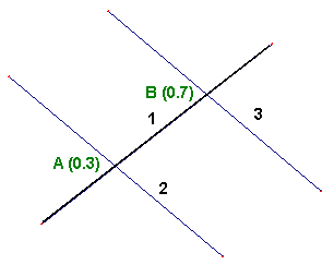
The following image shows the number 1 member trim operation by using number 2 and 3 members. Point A denotes the cut point of number 1 and 2 members (0.3 value denotes a relative coordinate of the member cut point along the member number 1), and point B denotes the cut point of the members number 1 and 3 (0.7 value denotes a relative coordinate of the member cut point along the member number 1).

In the Trim dialog the following parameters are specified:
- Trim object in the Member/Object field - member number 1
- Trim Object Selection field: members number 2 and 3.
Which part of the member number 1 is trimmed depends on the selection of the point coordinate on the trimmed part of the member.
Example 1
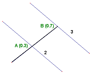
In the Relative Coordinate of the trim object part field, the value from the (0, 0.3) interval 0.1 is entered. The trim operation result is shown as follows:

Example 2
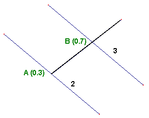
In the Relative Coordinate of the trim object part field, the value from the (0.3, 0.7) interval 0.5 is entered. The trim operation result is shown as follows:

Example 3
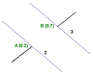
In the Relative Coordinate of the trim object part field, the value from the (0.7, 1.0) interval 0.9 is entered. The trim operation result is shown as follows:
