When generating a structure from an ACIS standard model (such as importing *.DXF, *.DWG, and *.SAT files) inconsistencies in the mesh between the edges of surface objects or between solid faces might occur. This can result from an incorrect structure model or an inaccurate replacement of a mathematical model with a discrete model used in the Robot program. To correct inconsistencies in the volumetric element mesh:
- Open the Shell Design structure type.
- Load the external file of the ACIS model (*.DXF, *.DWG, or *.SAT).
- Assign any temporary thickness to the structure so that a surface element mesh can be generated.
- Generate a calculation model to generate the element mesh.
- Correct the mesh manually:
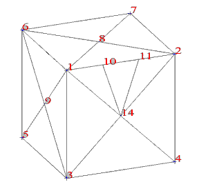
Manual correction consists in shifting the nodes that caused the inconsistency. For example, for the structure in Figure 1, the mesh is inconsistent on the edge 1÷2, where the sides of three elements meet with the side of one element. To correct the mesh, select node 10 and shift it to node 1. Next, select node 11 and shift it to node 2. Then, delete the coinciding nodes and distorted elements that were created when shifting the nodes 10 and 11.
- Delete the coinciding nodes and distorted elements using Edit menu > Correct.
- Change the structure type to Volumetric Structure Design (click Geometry menu > StructureType)
- Open the dialog for solid definition (click Geometry menu > Solids) and select Creation with: list of surface elements that define a solid. Next, select Delete surface elements, then select the entire structure using Add to create a solid.
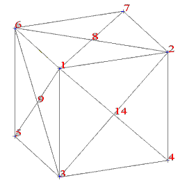
Figure 2 shows the final result of correcting the volumetric structure. If a shell structure needs to be corrected, then completing Steps 1 to 6 is sufficient.

Fig.1 Shows inconsistent mesh in a volumetric structure - edge 1÷2

Fig.2 Mesh after performing the correction