After clicking ![]() on the Offsets dialog, a new dialog for defining an offset is displayed.
on the Offsets dialog, a new dialog for defining an offset is displayed.
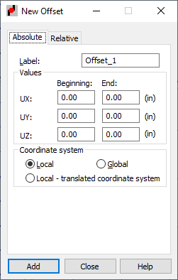
The New Offset dialog has 2 tabs:
- Absolute
- Relative.
On the Absolute tab, an offset value is defined by specifying a value of the shift in the direction of selected axes. This offset value does not change regardless of the operations performed on the elements on which the offset was defined.
On the Relative tab, an offset value is defined in relation to other existing objects. A basic feature of this offset type is automatically fitting an object to objects that already exist. (Fitting the length of a selected object to other defined objects, that is, the length increases or decreases as well as changing the position of one object with respect to another).
The difference between the absolute (manual) and relative (automatic) offset is shown in the following 2 examples:
Example 1
Changing a section of a column adjoining to a beam
-
Absolute (manual) offset
After the geometry of the beam-column connection is defined, an offset equal to one-half the height of the column section is defined.
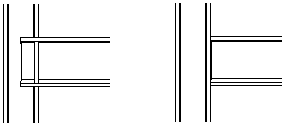
After changing the column section, the offset is not updated. The offset value still equals one-half the height of the previous section.

-
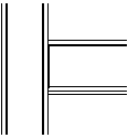
Relative (automatic) offset
After the geometry of the beam-column connection has been defined, an offset equal to one-half the height of the column section is defined.

After changing the column section, the offset is updated to the new column section. Elements adjust to each other.
Example 2
Changing the position of an object with respect to a selected object
-
Absolute (manual) offset
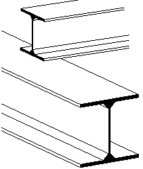
A beam-beam connection.
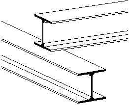
After changing the beam section, the offset is not updated. The offset value does not change.

-
Relative (automatic) offset
A beam-beam connection.

After changing the beam section, the offset is updated to the new section of the second beam. Elements adjust to each other.
Description of the Absolute tab:
- Specify a name in the Label field and offset values at the beginning and or the end of the bar:
UX - Beginning , UX - End, UY - Beginning, UY - End, UZ - Beginning, and UZ - End.
- From the Coordinate system field you can select the following coordinate systems:
- Local - When selected, offset values are displayed in the bar's local coordinate system.
- Global - When selected, offset values are displayed in the bar's global coordinate system.
- Local - translated coordinate system (when selected, values of offsets are given in the coordinate system associated with the local coordinate system of a translated bar). Note: A relative offset cannot be defined in the global system.
- At the bottom of the dialog, information about values of relative offsets is provided (offsets defined on the Relative tab).
See also:
Offset definition in the local/global system
The Relative tab has 2 parts: Cross-section and Member length.
- Cross-section has the following buttons:
- Section position
Automatically defines an offset for structure bars. The offset is defined by a shift of a bar axis to extreme section dimensions (only). An automatic offset is defined in the Position with Respect to Section dialog that opens after clicking Section position.
You can find information about the section shift with respect to the axis (vz,vpz,vy,vpy,0) under the Section position button.
- Axis offset
Automatically defines an offset for structure bars. The offset is defined by selecting an object to which the offset additionally refers. This object can be both a bar and a panel defined in a structure. This offset type is defined in the Position of the axis with respect to the section dialog that opens after clicking Axis offset.
For this offset type, you must give the number of a reference object. The object (bar or panel) number can be entered in the field or the object can be selected in the drawing area.
You can find information about the reference object (section) and the shift value: vy, vpy, vz, vpz, 0 under the Axis offset button.
- Section position
- Member length
Member length has 2 selection lists. The first list refers to the beginning of the member; whereas, the other list refers to the member end. The list comprises the following positions: in the axis, reduce length, and increase length.
Operation of the relative offset:
- Length reduction/increase
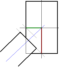
The relative offset (length increase/reduction) is calculated automatically. Its value is the greatest cross dimension of all the elements adjoining to a given node. When an element is set at an angle, the projection of dimensions on the X axis of the adjoining element is considered and the element length is reduced or increased to fit the dimension resulting from the projection.
- Cross-section
Similarly to shifting the section with respect to an axis, you specify the point on the reference object, with which to associate the axis of the element that is assigned an offset. This offset is intended for typical cases, such as, purlins supported by a spandrel beam.
Note: The transverse relative offset on bars rotated by a gamma angle might not work correctly. Correct operation of this option is only possible if axes of both elements in relation to which the offset will be defined remain compatible (such as, the Z axis of the local coordinate system of the first element is compatible with the Z axis of the local coordinate system of the other element).Note: If one offset type is assigned to several objects, then changes to the offset value will be connected with changes to the dimensions of the object indicated as a reference object.