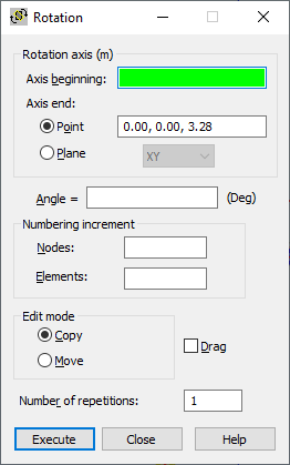
You can rotate structure nodes or elements, using either method:
- Click Edit menu > Edit > Rotate.
- Click
 .
.

To define the rotation, set the main parameters in the following fields of the Rotation dialog:
- Nodes - Specifies the node numbering increment when defining new nodes.
- Elements - Specifies the element numbering increment when defining new elements.
- Move - When selected, the selected node or element is moved in the structure (origin node or element changes its location in the structure).
- Copy - When selected, new nodes or elements are created in a structure (origin nodes or elements remain the same).
- Drag - When selected, additional elements are created between existing nodes and those nodes created during editing. These elements are numbered automatically.
- Number of repetitions - Defines the number of repetitions for edit operations. The edit option can be repeated while changing the active selection for recently created elements or nodes.
You define the values for the rotation axis coordinates and the rotation angle in the following fields:
- Axis beginning
- Axis end
- Angle.
After you have defined the rotation angle graphically, Robot rotates the selected nodes or elements; or if no objects have been selected, click Select in the context menu to select them. Robot remains in the Rotation mode until the next command is selected or the <Esc> key is pressed.
If you manually define the rotation axis and angle in the Rotation dialog, clicking Execute completes the action.
After you select the Grid or Auto cursor mode, the co-ordinates of the points describing the symmetry axis are displayed in the Axis beginning and Axis end fields. If the Node cursor mode is selected, the numbers of nodes defining the symmetry axis are displayed in the Axis beginning and Axis end fields. The display in the Rotation axis field depends on the cursor mode:
- Grid or Auto mode: Rotation axis (m, m, m)
- Node mode: Rotation axis.
You can define the rotation axis using either method:
- Using two points (recommended in the 3D view)
- Using a point and a plane (recommended in the 2D view)