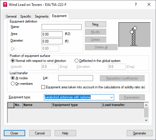
Opening the Wind Load on Towers dialog and clicking the Equipment tab displays the following dialog.

The options on this tab define additional surfaces that have significant influence on structure loading with wind, such as antennas, tables, structure fillings, and so on.
To define additional surfaces for a structure:
- Surface name
- Active surface exposed to wind operation
- Diameter - The diameter of the antenna belonging to the equipment (an antenna must be selected from the Equipment type list)
- Wind pressure coefficient CA
- Position of equipment surface field - Specifies the manner in which the equipment surface is to be treated. If the option Normal with respect to wind direction is selected, Robot assumes the surface is always perpendicular to the wind direction, regardless of the actual wind direction. If the option Deflected in the global system is selected, the position of the equipment surface is determined based on the values specified for the inclination angles of the surface in the global coordinate system. Azimuth is the inclination angle between the surface and the OXZ vertical plane of the global coordinate system. Elevation is the inclination angle between the surface and the OXY horizontal plane of the global coordinate system.
- Load transfer field - A load from additional surfaces is transferred to the structure through either bars or in structure nodes. In the List field, enter the relevant list of nodes or bars that will receive the transferred load. Clicking Repartition coefficient , opens the dialog for defining the coefficients that determine which part of the total load is to be distributed over the individual elements. The following principle of calculating a load value for individual elements is valid: repartition coefficients are summed up and the sum is treated as 100% of the load value; individual elements receive the part of the load proportionate to the coefficient defined for a given element.
- The option Equipment area taken into account in the calculations of solidity ratio (e) - When selected, the equipment area is accounted for in the calculations of the solidity ratio (e) for a structure wall. It applies to walls adjacent to bars on which the equipment is fixed. By default, the solidity ratio (e) value is calculated only based on the bars belonging to the wall and the fixed equipment is not considered in its calculations.
- Equipment type - In the Equipment type field, the following types are available: paraboloid antennas with radome, paraboloid antennas without radome, paraboloid antennas with cylindrical shroud, grid antennas, conical horn reflector antennas, passive reflectors, and other equipment types.
Note: All additional structure elements (structure equipment) that are not positioned in the plane of the structure walls should be defined only on the Equipment tab in the dialog. The equipment should not be modeled using structure bars, because errors might result in the algorithm recognizing structure walls.