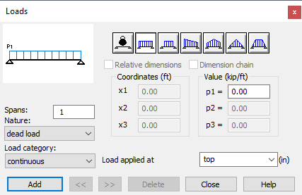
Click ![]() Load definition or select RC element > Loads to define the load to be applied to the designed deep beam.
Load definition or select RC element > Loads to define the load to be applied to the designed deep beam.

- Define a load to be applied to a designed deep beam as follows.
- Enter the numbers of spans to which the load will be applied in the Spans field. Typing the letter A here results in selection of All deep beam spans.
- Select the load nature (dead, live, seismic and so on) from the Nature list.
- Select the type of load to be applied (continuous, concentrated or planar) from the Load category list.
- Define whether the load is to be applied to the lower or upper edge of the deep beam. It is also possible to specify an arbitrary level of load application measured from the lower edge of the deep beam.
- Define the value of the selected load type and click Add.
The left part of the Loads dialog changes based on the selected load type. It displays a scheme of the selected continuous or concentrated or planar load type. To the right are the load selection icons.
Below the Load Type icons is located the Relative Dimensions field. If this option is active, (the symbol √ appears), relative concentrated coordinates will be used in defining the load position (included in the <0,1> interval). If this option is inactive, the concentrated coordinates will be give in the length units chosen by the user.
If continuous load type is selected, the Dimension Chain option appears. If this option is active, (the symbol √ appears), a so called dimension chain will be used while defining a continuous load. This signifies that the continuous p2 load value will be applied at a concentrated with the coordinate (x1+x2), the p3 load value at a concentrated with the coordinate (x1+x2+x3) etc.If the option is inactive, the load p1 is applied at a concentrated with the coordinate x1, the load p2 at a concentrated with the coordinate x2 etc.
In the case of a concentrated load, Coordinates and Value contain the x1, x2, n and F or M parameters. Defining parameters x2 and n allows one to define a group of concentrated loads. Particular symbols refer to the following quantities.
 |
x1 - Distance between the first force/moment application point. x2 - Spacing of successive concentrated forces/moments. n - Number of concentrated forces/moments. F or M - Value of a concentrated force / moment. |
Moreover, for a concentrated force load there is also a field for defining the width of the L distribution. This denotes the width onto which a load is distributed, such as a beam resting on a deep-beam.
A detailed description of the principles concerning the distribution of concentrated loads on a given width is provided in the topic Principles of deep-beam modeling by means of FEM - Modeling of concentrated loads. When distributing a load on a given width, a point where the load is applied is treated as the load axis and falls in the midpoint of the segment along which the force is distributed.
If it is necessary to define a load applied at a point (without distributing the force), a distribution width L=0 may be defined.
In a continuous load, the Coordinates field contains the following options: x1, x2, x3, x4 (fields for entering the coordinate value of the characteristic point at which the selected kind of the continuous load is applied), p1, p2, and p3 (fields for entering the coordinate value of the characteristic point at which this load is applied (for the x1, x2, x3 coordinates, respectively).
The point is shown on the drawing in the upper left corner
In a planar load, the Coordinates field can be alpha, beta, or y. You can define the value p of the load (load per area unit). The load is converted into a continuous load. The following types of the planar load are available.

|
Loads gathered from the plate surface between two beams. Define the distance y from which the loads are gathered. |

|
Loads gathered from the plate surface is delimited by four beams. Define alpha and beta angles. |

|
Loads gathered from the plate surface is delimited by four beams. Define alpha and beta angles, as well as the distance y. |