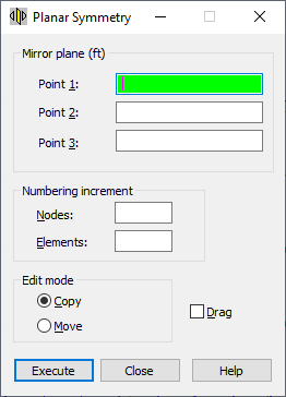
Open the Planar Symmetry dialog to define planar symmetry for structure nodes or elements, using either method:
- Click Edit menu > Edit > Planar Symmetry.
- Click
 .
.

To define the 3D mirror, set the main parameters in the following fields of the Planar Symmetry dialog:
- Nodes - Defines the node numbering increment when defining new nodes.
- Elements - Defines the element numbering increment when defining new elements.
- Move - When selected, the selected nodes or elements are moved in the structure (origin nodes or elements change their location in the structure).
- Copy - When selected, new nodes or elements are created in a structure (origin nodes or elements remain the same).
- Drag - When selected, additional elements are created between the existing nodes and the nodes created during editing. The elements are numbered automatically.
Also, define the coordinates of the points defining the symmetry plane (fields: Point1, Point2 and Point3).
To define these points use either method:
- Graphic - (cursor changes its shape to a cross) - Point the cursor to either the first point of the mirror plane or the node indicating the first point. Point coordinates or the appropriate node number display automatically in the field.
- Manual - Enter either the coordinates of the first point of the mirror plane or the appropriate node number in the field.
After you have defined graphically the coordinates or number of points for the plane, the planar symmetry for the selected nodes or elements is created; or if no objects have been selected, click Select in the context menu to select them. Robotremains in planar symmetry mode until the next command is selected or the <Esc> key is pressed.
When you have manually defined the points for the plane in the field, clicking Execute completes the action.
After the Grid or Auto cursor mode is selected, the coordinates for the points describing the planar symmetry are displayed in the Point 1, Point 2, and Point 3 fields. If the Node cursor mode is selected, the number of nodes defining the planar symmetry plane is displayed in the Point 1, Point 2, and Point 3 fields.