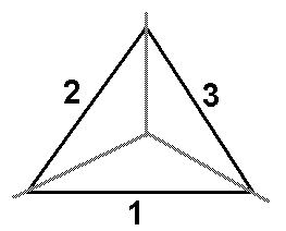
The algorithm recognizing geometry is designed to determine which structure elements belong to individual structure walls. The following image shows a cross section of a structure with a triangular base:

A given structure element is assigned to one or two zones from the 3 zones 1, 2, and 3 of the individual structure walls.
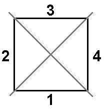
The next image shows a cross section of a structure with a square base.

A given structure element is assigned to one or two zones from the 4 zones 1, 2, 3, and 4 of the individual structure walls.
During code calculations, Robot calculates the area of the bars that belong to individual structure walls. Problems recognizing to which structure wall a given bar belongs might cause errors in calculating the areas of the elements belonging to individual walls.
For the structure geometry to be recognized correctly, nodes and bars should not be positioned on the structure axis.
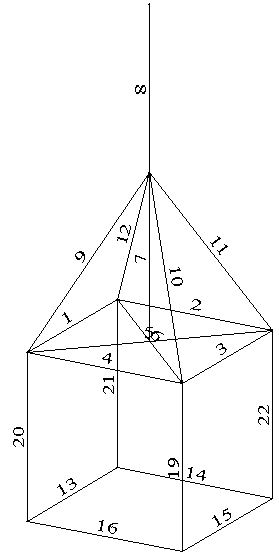
The following image shows parts of a structure that are not recognized correctly.

Elements 7 and 8 will not be recognized correctly, because they are located on a structure axis on the border of four zones. Elements 5 and 6 will not be recognized correctly, because they pass through the structure axis. Elements 9, 10, 11, 12 will not be recognized correctly, because one of the nodes is positioned on the structure axis.
It is recommended that all additional structure elements (structure equipment) that do not lie in the plane of a structure wall, be defined on the Equipment tab in the Wind Load on Towers dialog. Equipment should not be modeled using structure bars, because it might cause errors in the algorithm that recognizes structure walls.
You can model part of the structure elements as elements positioned outside the planes of a structure wall. When there are problems with geometry recognition, a message is displayed, and the calculations are performed in an approximate manner.