Open the Polyline Contour dialog, which defines various line types (broken or contour), using either method:
- Click Geometry menu > Objects > Polyline-Contour.
- Click
 .
.
This dialog is available for the structure types: plate and shell.
This dialog box has 4 parts:
- Object field, which specifies the number or identifier for the created or selected object
- Definition Method
- Geometry
- Parameters.
When the Polyline Contour dialog is fully opened, then clicking one of the 3 buttons: Definition Method, Geometry, or Parameters minimizes the corresponding part of the dialog so it displays only the options used at a given time. When the window is minimized, clicking one of the button extends the dialog:
Definition Method
Options to define the line are found in the Definition Method field of the dialog. The following diagrams show the different methods to define a line:

|
Line is defined using two points: beginning and end of the line. |

|
Broken line (polyline): the line is defined by specifying the consecutive points of the line. |

|
Contour: the line is defined by specifying consecutive points on the contour. |
Geometry
The fields for defining the object in Geometry depend on the option selected in Definition Method. If Line is selected, fields for entering the coordinates of points P1 and P2 (line beginning and line end) are displayed. When selecting Polyline or Contour, a list to define the consecutive points of an arc or a segment are displayed. The Polyline and Contour options are used when defining plate-shell or volumetric structures.
When the following icons are selected in Geometry:
|
|
A segment of a contour or polyline is defined. |
|
|
An arc is defined (beginning, middle, and end of the arc). |
|
|
An arc is defined (beginning, end, and middle of the arc). |
Clicking
![]() opens the
Contour dialog.
opens the
Contour dialog.
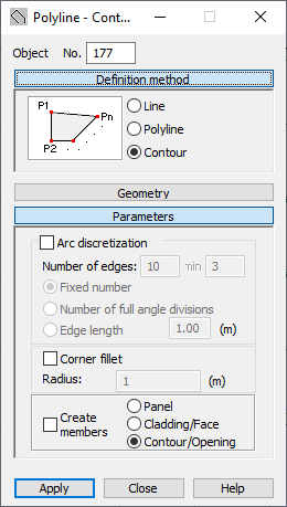
Parameters
In Parameters, there are many options.
- Arc discretization has options for determining discretization parameters for contour or polyline arcs.
When Arc discretization is selected, an arc is created using the analytical method. You can also define parameters for dividing an arc:
- When Fixed number is selected, the arc is divided into the number of elements defined in the Edges field.
- When Number of full angle divisions is selected, the number entered in the Edges field indicates the number of full angle (360 degrees) divisions and Min defines the smallest number of full angle divisions (the default setting is 3). The arc is always divided into equal-length segments, which means that the defined number of full angle divisions might not match the number of equal-length segments. When this happens, Robot automatically matches the number of arc divisions that permits the arc to be divided into equal-length segments
- When Edge length is selected, the number specifies the lengths for the sides of the polygon approximating the arc (the polygon inscribed into the arc).
- The Corner fillet option defines a polyline or contour as segments. Connections of two consecutive segments of a polyline or contour are rounded. A value for the fillet radius can be specified in the Radius field.
-
Create members
When Create members is cleared, the options: Panel, Cladding/Face and Contour/Opening become available:
- When Panel is selected for a contour, by default a number and panel properties are assigned (thickness, reinforcement method, material) to the object.
- When Cladding/Face is selected for a contour, a number is assigned to the object. The object is defined as a face without the assigned properties such as reinforcement type and thickness; however, cladding parameters can be specified. You can use this type of object the following ways:
- When creating a volumetric structure (solid), it can constitute a face of a volumetric object
- When distributing planar loads onto members, the cladding attribute determines the method and direction of load distribution. Arbitrary loads (planar, linear, and point loads) can be applied to a cladding, a next distributed on members.
- When Contour/Opening is selected, the arc is only a contour and is assigned neither panel nor cladding properties. When this type of contour is within a panel or another contour, then an opening is created in it. If a contour is assigned:
- Thickness, the contour is a panel.
- Cladding, the contour is a face.
You can define a line (polyline or contour) in the following ways:
- Select a method for defining the line (line, broken line or contour definition)
- Select the object geometry:
- Text: specifying coordinates of individual points in the Geometry field of the dialog and clicking Apply.
- Graphic: click in the appropriate field under Geometry in the dialog, switch to the drawing area and click the point indicating the first point on the line, polyline, or contour and click the consecutive points.
- A method combining the graphic and text methods.