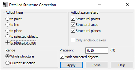
Open the Detailed Structure Correction dialog, which lets you correct the geometry of a defined structure, by clicking Edit menu > Detailed Correct.

Structures created in Robot or loaded from *.dxf or *.igs files might require certain modifications, for example, shifting nodes to a different position. You can use the Detailed Structure Correction dialog for this.
The options in this dialog let you change the position of structure nodes or the characteristic points of structure objects (e.g. apexes of a plate contour, points defining an arc, points defining a cone, and so on.). Nodes or characteristic points of structure objects can be moved (adjusted) to:
- Point - In the Adjust parameters field, you specify the coordinates of the point to which to move a node.
- Line - In the Adjust parameters field, you must specify the coordinates of 2 points defining a line; the nodes are moved (projected) onto the defined line.
- Plane - In the Adjust parameters field, you must specify the coordinates of 3 points defining a plane; the nodes are moved (projected) onto the defined plane.
- Selected objects such as: structure nodes or bars, panels, and objects (nodes are moved onto the characteristic lines of the objects).
In the case when part of a structure is adjusted to the selected objects of a structure, you should:
- In the Adjust type field, click to selected objects
- In the Adjust parameters field, enter or select graphically, the nodes or bars, panels, or objects to which the nodes or characteristic points will be moved.
- In the Range field, you should click Current selection and graphically select the part of the structure which is to be corrected.
Note: When Range: current selection is first selected, and then Adjust parameters are determined before selecting the objects for current selection, you should choose from the shortcut menu the Select option. Otherwise, the selected objects are added to the field in the Adjust parameters field. - To defined structure axes - There are 3 ways to do this in the Adjust parameters field: nodes can be moved to the nodes that are intersections of the structure axes, to structure axes, and to planes defined by the structure axes.
At the bottom of the dialog, there are 2 options: Whole structure or Current selection. They indicate the range for correcting a structure. Additionally, precision can be determined, which is a distance value defining the range in which corrections for a structure are performed. Structure corrections are performed only then when the distance is smaller than precision. If Mark corrected objects is selected, then after the structure model is corrected, the objects (bars, panels, and so on) in the drawing area, whose geometry were changed are selected.
To perform structure correction:
- Select the type to adjust, under Adjust type.
- Depending on the adjust type, determine the adjust parameters. Determine the point, line, or plane to which nodes or characteristic points of a structure will be moved.
- Specify if the correction is for a whole structure or only for selected structure elements.
- Define a precision value.
- Click Apply.
See also: